2 general precautions, 3 cable types, General precautions -2 – Yokogawa ADMAG AXF User Manual
Page 9: Cable types -2
IM 1E10C1-E
3-2
3. INSTALLATION
3.2.2
General Precautions
Please give attention to the followings in wiring.
CAUTION
• Please pay attention to avoid the cable is
bended excessively.
• Please do not connect cables outdoors in case
of rain to prevent damages from dew formation
and to keep insulation inside the terminal box
of the flowmeter.
• The all cable ends are to be provided with
round crimp-on terminal.
• The power cables and output signal cables
must be routed in separate steel conduit tubes
or flexible tubes.(except 4-core 24VDC cable
wiring.)
• When waterproof glands or union equipped
waterproof glands are used, the glands must be
properly tightened to keep the box watertight.
• Please install a external switch or circuit
breaker as a means of power off (capacitance;
15A, conform to IEC947-1 and IEC947-3). The
preferable location is either near the instrument
or other places to easy operation. Further-
more, please indicate "power off equipment" on
the those external switch or circuit breaker.
• Please be sure to fully tighten the terminal box
cover before the power is turned on. After
tightening the covers, please be sure to fix it
with the special screw using a hexagonal
wrench attached.
• Please be sure to turn off the power before
opening the terminal box cover.
• In case of DC power supply, a plug is attached.
When 4-core cable is used, please put that
plug into unused electrical connection port.
3.2.3
Cable Types
(1) Dedicated Signal Cable(AM011)
The flow signal is transmitted via this dedicated cable.
The cable is constructed with double shielding over the
two conductors, and used heat-resistant vinyl as the
outer jacket material.
Finished diameter:
10.5 mm (0.413 in.)
Maximum length:
30 m (98 ft)
Maximum temperature: 80
°
C (176
°
F)
Outer jacket
10.5mm
(0.413in.)
Tape
Shield
Insulation
Insulation
F030202.EPS
Shields
Conductors
Figure 3.2.2
Dedicated Signal Cable AM011
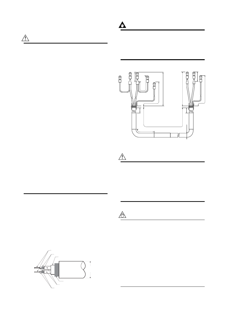
IMPORTANT
If the cable is longer than required, cut off any
extra length, rather coiling it up, and terminate
the conductors as shown in Figure 3.2.3. Avoid
using intermediate terminal boards to extend the
cable length, or this will interrupt the shielding.
20 (0.8)
ø10.5 (0.4)
AM011*A
L (SPECIFIED LENGTH)
150
(5.9)
8 (0.3) Max.
150 (5.9)
80 (3.15)
70 (2.76)
90 (3.5)
55 (2.2)
90 (3.5)
50 (1.97)
25 (0.98)
SA
SB
A
C
B
A
C
B
8 (0.3) Max.
(WHITE)
(BLACK)
(RED)
(WHITE)
(BLACK)
Unit : mm (inch)
(RED)
F030203.EPS
On the
converter side
On the flow
tube side
Figure 3.2.3
Treatment of Dedicated Signal Cable
CAUTION
Since A, B, SA, SB, and C all operate at differ-
ent electrical potentials, securely insulate them
from each other so they do not touch.
The shields must not be allowed to touch each
other or to touch the case.
Cover each shield with vinyl tube or wrap in vinyl
tape.
NOTE
Conductors A and B carry the signal from the
electrodes, and C is at the potentials of the liquid
it self (signal common) . Shields SA and SB are
kept at the same potentials as the individual
electrodes (these are actively driven shields).
This is done to reduce the effect of the distrib-
uted capacitance of the cable at long cable
length. Note that, since the signals from the
individual electrodes are impedance converted
inside the converter, errors will result if they
come in contact with any other component.
Great care must be taken in the cable end
treatment.