Caution – Proface PS4800 - 19 Panel PC" User Manual
Page 132
Hardware Modifications
132
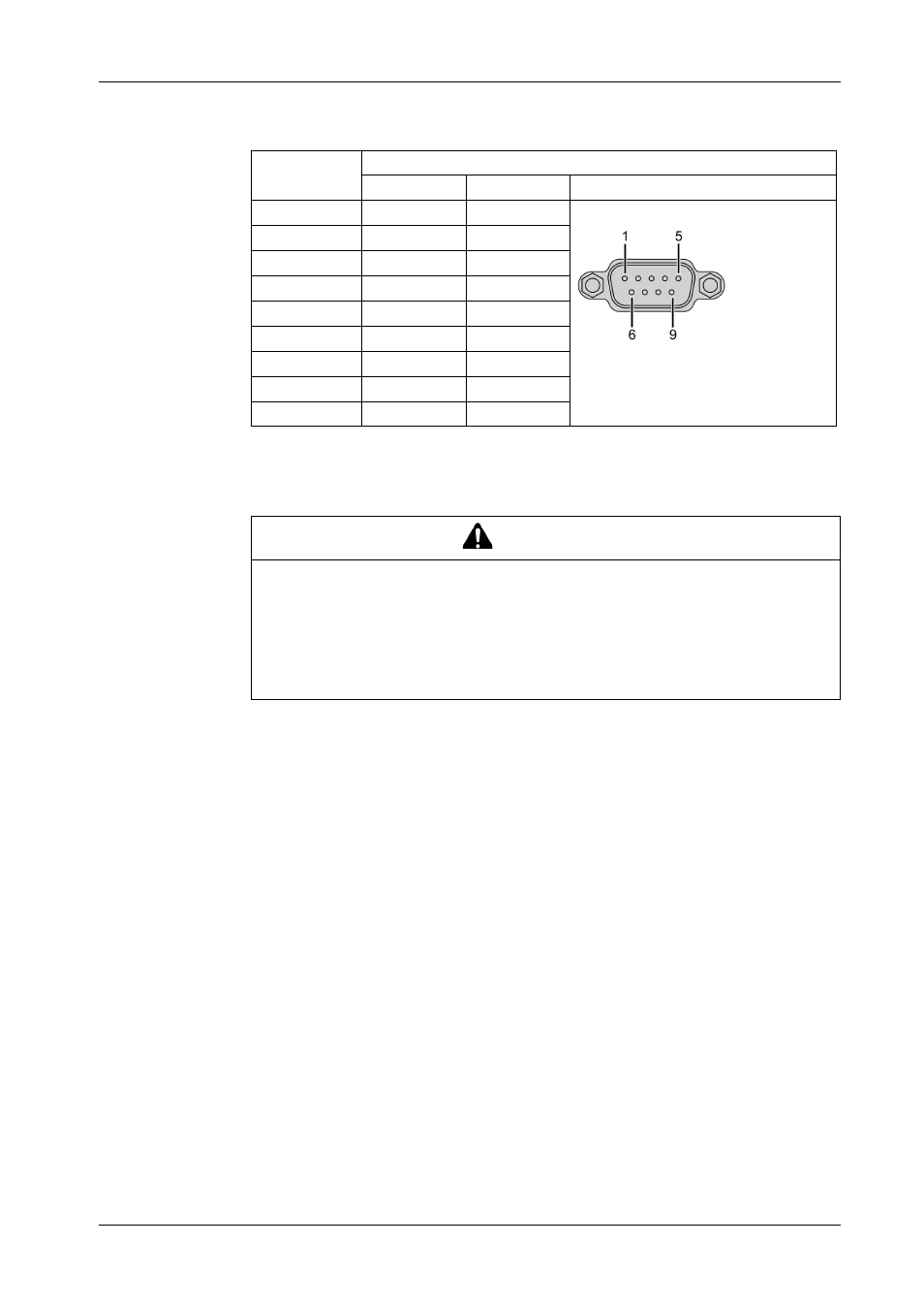
The table shows the D-Sub 9 pin assignments:
Any excessive weight or stress on communication cables may disconnect the
equipment.
RS485 Interface Specificity
NOTE: The pins of the RS422 default interface (1, 4, 6 and 9) should be used for
operation.
The RTS line must be switched each time the driver is sent and received. There is
no automatic switch back. This cannot be configured in Windows.
The voltage drop caused by long line lengths can lead to greater potential
differences between bus stations, which can hinder communication. You can
improve the communication by running a ground wire with the other wires.
Pin
Assignment
RS232
RS422/485
1
N.C.
TXD\
D-Sub9 pin plug connector:
2
RXD
N.C.
3
TXD
N.C.
4
N.C.
TXD
5
GND
GND
6
N.C.
RXD\
7
RTS
N.C.
8
CTS
N.C.
9
N.C.
RXD
CAUTION
LOSS OF POWER
Ensure that communication connections do not place excessive stress on the
communication ports of the Industrial Personal Computer.
Securely attach communication cables to the panel or cabinet.
Use only D-sub 9 pin cables with a locking system in good condition.
Failure to follow these instructions can result in injury or equipment damage.