Operation, B-39 – Lincoln Electric IM10077 POWER FEED 25M User Manual
Page 55
B-39
OPERATION
B-39
POWER FEED™ 25M
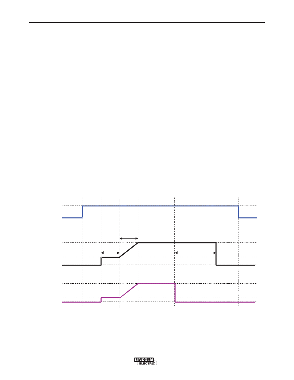
EXAMPLE 2 - 2 STEP TRIGGER: Improved Arc Start
and Arc End. Tailoring the arc start and arc end is a
common method for reducing spatter and improving
weld quality. This can be accomplished with the Start
and Burnback functions set to a desired values and
Crater set to OFF. (See Figure B.20)
For this sequence,
PREFLOW:
Shielding gas begins to flow immediately when the
gun trigger is pulled.
RUN-IN:
After preflow time expires, the power source regulates
to the start output and wire is advanced towards the
work piece at the Run-In WFS. If an arc is not estab-
lished within 1.5 seconds, the power source output
and wire feed speed skips to the weld settings.
UPSLOPE:
Once the wire touches the work and an arc is estab-
lished, both the machine output and the wire feed
speed ramp to the weld settings throughout the start
time. The time period of ramping from the start set-
tings to the weld settings is called UPSLOPE.
WELD:
After upslope, the power source output and the wire
feed speed continue at the weld settings.
BURNBACK:
As soon as the trigger is released, the wire feed
speed is turned OFF and the machine output contin-
ues for the burnback time.
POSTFLOW:
Next, the machine output is turned OFF and shielding
gas continues until the post flow timer expires.
Shielding
Gas
I dle
Preflow
St r i
ke
Up slope
Weld
Bur nbac k
Pos t f l
ow
I dle
WFS
On
Of f
Run- in
Of f
Weld
Of f
Weld
Ar
c
E
s
t
a
b
lis
h
e
d
Tr
i
g
g
e
r
P
u
lle
d
T
r
i
gger
Re
l
e
a
s
e
d
2 Step Trigger
Star t = O
N
Cr ater = OFF
Bur nback = ON
1.5 sec max.
St art
Star t ti me
Bur nbac
k Ti m
e
Power
Sour ce
Output
FIGURE B.20