Installation, Warning – Lincoln Electric IM10077 POWER FEED 25M User Manual
Page 12
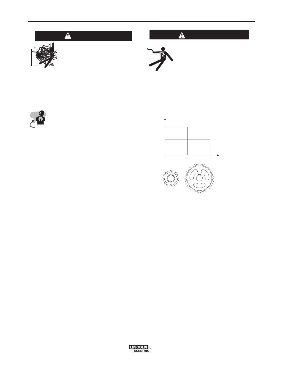
CHANGING THE DRIVE MOTOR GEAR RATIO
• Turn off input power at the weld-
ing power source before installa-
tion or changing drive roll and/or
wire guides.
• Do not touch electrically live parts
such as the wire drive or internal
wiring.
• When feeding with the gun trigger, the electrode
and wire drive mechanism are "hot" to work and
ground and could remain energized several sec-
onds after the gun trigger is released.
• Only qualified personnel should perform this
operation.
------------------------------------------------------------------------
Tools required:
• 1/4" hex key wrench
• 3/4" open end wrench
• 9/16" socket and ratchet wrench
• 7/16" nut driver
• 5/16" nut driver
• Phillips screw driver
1. Turn power off at the welding power source.
2. Remove the spool of electrode from the wire feeder.
3. Loosen the thumb screw at the wire drive and remove the
welding gun.
4. Remove the outer wire guide, drive rolls and inner wire
guide.
5. Use a 7/16" nut driver to remove the gear cover.
6. Use 9/16" socket and ratchet wrench to remove the lower
drive roll hub retainer. Remove the lower drive roll hub.
7. With a Phillips screwdriver, remove the screw, washer
and collar holding the pinion gear. Remove the pinion
gear.
WARNING
Extra Torque
Gearing
Normal Speed
Gearing
Extra
Torque
Gearing
Normal
Speed
Gearing
400
800
WFS
Feed Force
A-5
INSTALLATION
POWER FEED™ 25M
A-5
SHIELDING GAS CONNECTION
CYLINDER may explode if
damaged.
• Keep cylinder upright and
chained to support.
• Keep cylinder away from areas where it may be
damaged.
• Never lift welder with cylinder attached.
• Never allow welding electrode to touch cylinder.
• Keep cylinder away from welding or other live
electrical circuits.
• BUILD UP OF SHIELDING GAS MAY
HARM HEALTH OR KILL.
• Shut off shielding gas supply when not
in use.
• See American National Standard Z-49.1, "Safety
in Welding and Cutting” Published by the
American Welding Society.
------------------------------------------------------------------------
M
AXIMUM INLET PRESSURE IS
100
PSI
. (6.9
BAR
.)
Install the shielding gas supply as follows:
1. Secure the cylinder to prevent it from falling.
2. Remove the cylinder cap. Inspect the cylinder valves
and regulator for damaged threads, dirt, dust, oil or
grease. Remove dust and dirt with a clean cloth. DO
NOT ATTACH THE REGULATOR IF OIL, GREASE
OR DAMAGE IS PRESENT! Inform your gas supplier
of this condition. Oil or grease in the presence of high
pressure oxygen is explosive.
3. Stand to one side away from the outlet and open the
cylinder valve for an instant. This blows away any dust
or dirt which may have accumulated in the valve out-
let.
4. Attach the flow regulator to the cylinder valve and
tighten the union nut(s) securely with a wrench. Note:
if connecting to 100% CO2 cylinder, insert regulator
adapter between regulator and cylinder valve. If
adapter is equipped with a plastic washer, be sure it is
seated for connection to the CO2 cylinder.
5. Attach one end of the inlet hose to the outlet fitting of
the flow regulator. Attach the other end to the welding
system shielding gas inlet. Tighten the union nuts with
a wrench.
6. Before opening the cylinder valve, turn the regulator
adjusting knob counterclockwise until the adjusting
spring pressure is released.
7. Standing to one side, open the cylinder valve slowly a
fraction of a turn. When the cylinder pressure gage
stops moving, open the valve fully.
8. The flow regulator is adjustable. Adjust it to the flow
rate recommended for the procedure and process
being used before making a weld.
WARNING