Operation – Lincoln Electric IM10077 POWER FEED 25M User Manual
Page 20
B-4
OPERATION
B-4
POWER FEED™ 25M
1
13
2
3
14
16
17
10
11
12
15
5
8
7
9
6
18
19
4
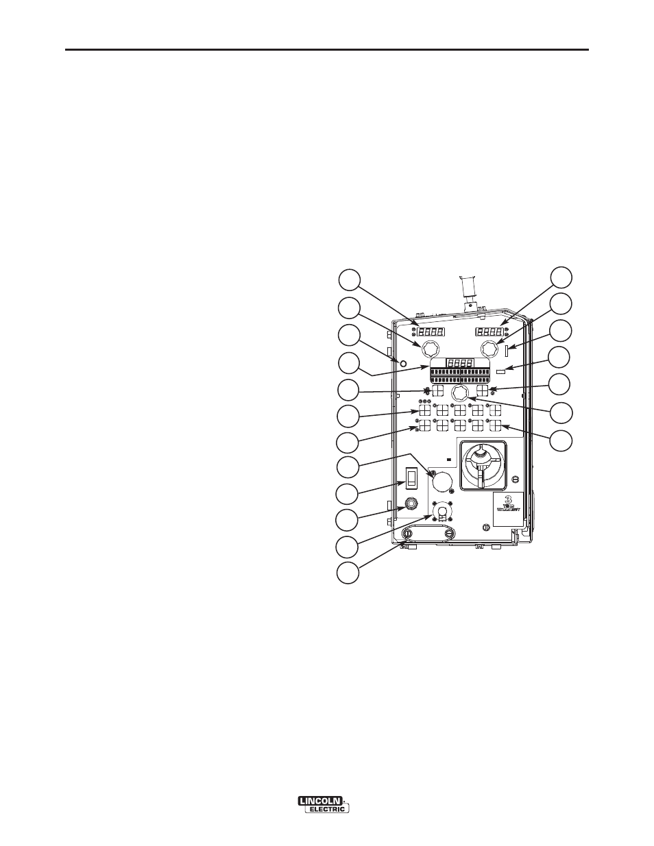
FIGURE B.1
CASE FRONT CONTROLS
(SEE FIGURE B.1)
1. Left DISPLAY window
Shows WIRE FEED SPEED or AMPERAGE.
2. Left KNOB
Adjusts values in left display.
3. Status LED
Illuminates a steady green when communicating to
the power source properly.
4. Main display
Shows detailed welding and diagnostic information.
5. Left Button
Changes the Main display to show the Weld Mode
or UltimArc.
6. Procedure Button
Selects A or B procedure, or gun control.
7. 2-Step/4-Step Button
Toggles between 2-step and 4-step trigger opera-
tion.
8. 5-pin connector
Trigger connector for a push-only gun.
9. ON/OFF switch
Controls power to the POWER FEED™ 25M.
10. 3 Amp Circuit Breaker
Protects the 12-pin accessories
11. 12-pin connector
Connection for push-pull guns, remotes
12. Cover
Covers location for optional water cooling line.
13. Right Display window
Shows VOLTAGE or TRIM.
14. Right Knob
Adjusts values in the right display.
15. Thermal
Lights when the drive overheats.
16. Set-Up
Lights when feeder is set-up.
17. Right Button
Changes the Main display to show Start Options or
End Options.
18. Set Knob
Changes the value on the Main display.
19. Memories Buttons
For selection of common procedures.