1 at/atx power mode jumper settings, Table 4-1: jumpers, Table 4-2: at/atx power mode jumper settings – IEI Integration KINO-QM670 v2.01 User Manual
Page 70
KINO-QM670 Mini-ITX SBC
Page 55
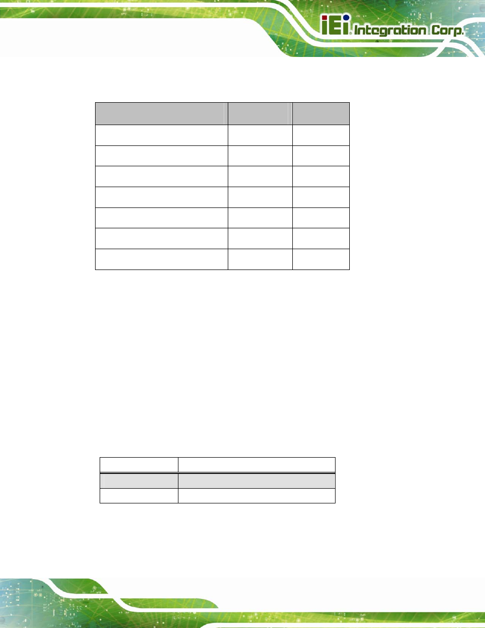
Before the KINO-QM670 is installed in the system, the jumpers must be set in accordance
with the desired configuration. The jumpers on the KINO-QM670 are listed in
7
Table 4-1.
Description
Type
Label
AT/ATX Power Mode Setting
3-pin header
J_ATXCTL1
Clear CMOS
3-pin header
J_CMOS1
LVDS Panel Resolution
8-pin header
J_PID1
LVDS Voltage Select
3-pin header
J_VLVDS1
ME RTC Register
3-pin header
ME_RTC1
Flash Security Override
3-pin header
J_FLASH1
MPC Switch Control (Reserved)
3-pin header
J_MPC1
Table 4-1: Jumpers
4.5.1 AT/ATX Power Mode Jumper Settings
Jumper Label:
J_ATXCTL1
Jumper Type:
3-pin header (1x3)
Jumper Settings:
See Table 4-2
Jumper Location:
See Figure 4-6
The AT Power Select jumper specifies the systems power mode as AT or ATX. AT/ATX
Power Mode jumper settings are shown in Table 4-2.
AT Power Select
Description
Short 1 - 2
Use ATX power
Short 2 – 3
Use AT power
Table 4-2: AT/ATX Power Mode Jumper Settings
The location of the AT/ATX Power Mode jumper is shown in Figure 4-6 below.