3 so-dimm installation, 5 jumper settings, Umper – IEI Integration KINO-QM670 v2.01 User Manual
Page 69: Ettings, Figure 4-4: so-dimm installation, Figure 4-5: jumper locations
KINO-QM670 Mini-ITX SBC
Page 54
4.4.3 SO-DIMM Installation
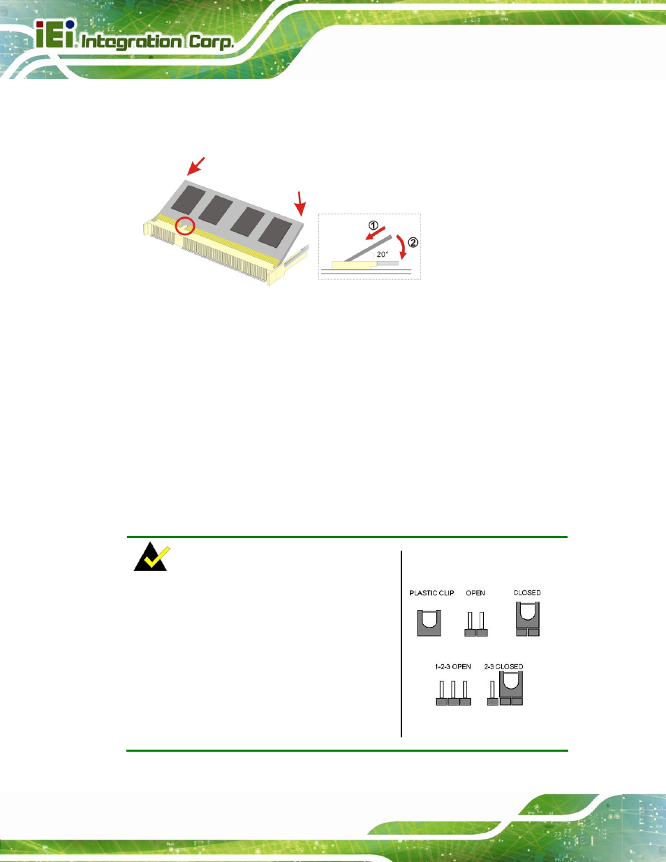
To install a SO-DIMM, please follow the steps below and refer to Figure 4-4.
Figure 4-4: SO-DIMM Installation
Step 1:
Locate the SO-DIMM socket. Place the board on an anti-static mat.
Step 2:
Align the SO-DIMM with the socket. Align the notch on the memory with the
notch on the memory socket.
Step 3:
Insert the SO-DIMM. Push the memory in at a 20º angle. (See Figure 4-4)
Step 4:
Seat the SO-DIMM. Gently push downwards and the arms clip into place. (See
Figure 4-4)
4.5 Jumper Settings
NOTE:
A jumper is a metal bridge used to close an
electrical circuit. It consists of two or three metal
pins and a small metal clip (often protected by a
plastic cover) that slides over the pins to connect
them. To CLOSE/SHORT a jumper means
connecting the pins of the jumper with the plastic
clip and to OPEN a jumper means removing the
plastic clip from a jumper.
Figure 4-5: Jumper Locations