6 external peripheral interface connection, 1 audio connector, Xternal – IEI Integration KINO-G410 v2.00 User Manual
Page 61: Eripheral, Nterface, Onnection, Figure 4-12: dual usb cable connection
KINO-G410 Min i-ITX Mo th e rb o a rd
P a g e 49
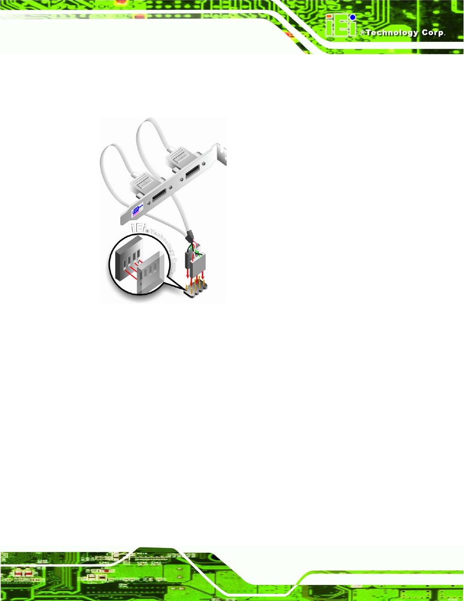
S te p 3:
Insert the cable connectors
.
Once the cable connectors are properly aligned
with the USB connectors on the KINO-G410, connect the cable connectors to
the on-board connectors. See Figure 4-12.
Figure 4-12: Dual USB Cable Connection
S te p 4:
Attach the bracket to the chassis. The USB 2.0 connectors are attached to a
bracket. To secure the bracket to the chassis please refer to the installation
instructions that came with the chassis.
S te p 0:
4.6 Exte rn a l P e rip h e ra l In te rfa c e Co n n e c tio n
This section describes connecting devices to the external connectors on the KINO-G410.
4.6.1 Au d io Co n n e c to r
The audio jacks on the external audio connector enable the KINO-G410 to be connected
to a stereo sound setup. To install the audio devices, follow the steps below.
S te p 1:
Identify the audio plugs. The plugs on your home theater system or speakers
may not match the colors on the rear panel. If audio plugs are plugged into the
wrong jacks, sound quality will be very bad.