2 peripheral interface connectors, 3 external interface panel connectors, Table 3–1: internal peripheral connectors – IEI Integration KINO-G410 v2.00 User Manual
Page 27
KINO-G410 Min i-ITX Mo th e rb o a rd
P a g e 15
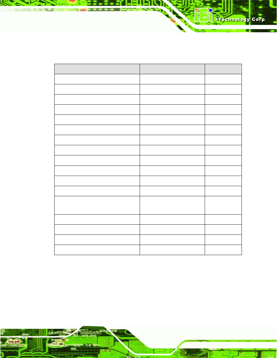
3.1.2 P e rip h e ra l In te rfa c e Co n n e c to rs
The table below lists all the connectors on the board.
Co n n e c to r
Typ e
La b e l
Battery connector
2-pin wafer
BAT1
Fan connector (CPU)
4-pin wafer
CPU_FAN1
Fan connector (system)
3-pin wafer
SYS_FAN1
CPU Power Input Connector
4-pin connector
CPU12V1
Digital I/O connector
10-pin header
DIO1
Front panel connector
14-pin header
F_PANEL1
Memory slot
204-pin DDR3 DIMM slot
DIMM1, DIMM2
Parallel port connector
26-pin header
LPT1
PCIe x16 slot
PCIe x16 slot
PCIEX16_1
Power connector
24-pin connector
ATX1
RS-232 serial port connector
10-pin header
COM4, COM5
RS-232/422/485 serial port connector
14-pin header
COM6
SATA drive connectors
7-pin SATA drive connectors
SATA1, SATA2,
SATA3, SATA4
SMBus connector
4-pin wafer
CN1
SPI Flash connector
8-pin header
JSPI1
USB connectors
8-pin header
USB45, USB67
VGA to LVDS connector
20-pin header
JP4
Table 3–1: Internal Peripheral Connectors
3.1.3 Exte rn a l In te rfa c e P a n e l Co n n e c to rs
The table below lists the connectors on the external I/O panel.