Warner Electric Advanced Technology Tension Clutches User Manual
Page 4
Complete Clutch Repair - On the Shaft
The new ATT design incorporates the latest in
advanced technology providing a rugged, durable,
patented design for long life, and maximum heat dis-
sipation. Patented, easy to replace, friction surfaces
extend the design life for continued like-new per-
formance. The ATT offers complete repair on the
shaft following ten easy steps. The repair can be
completed utilizing the parts in the friction face
replacement kit.
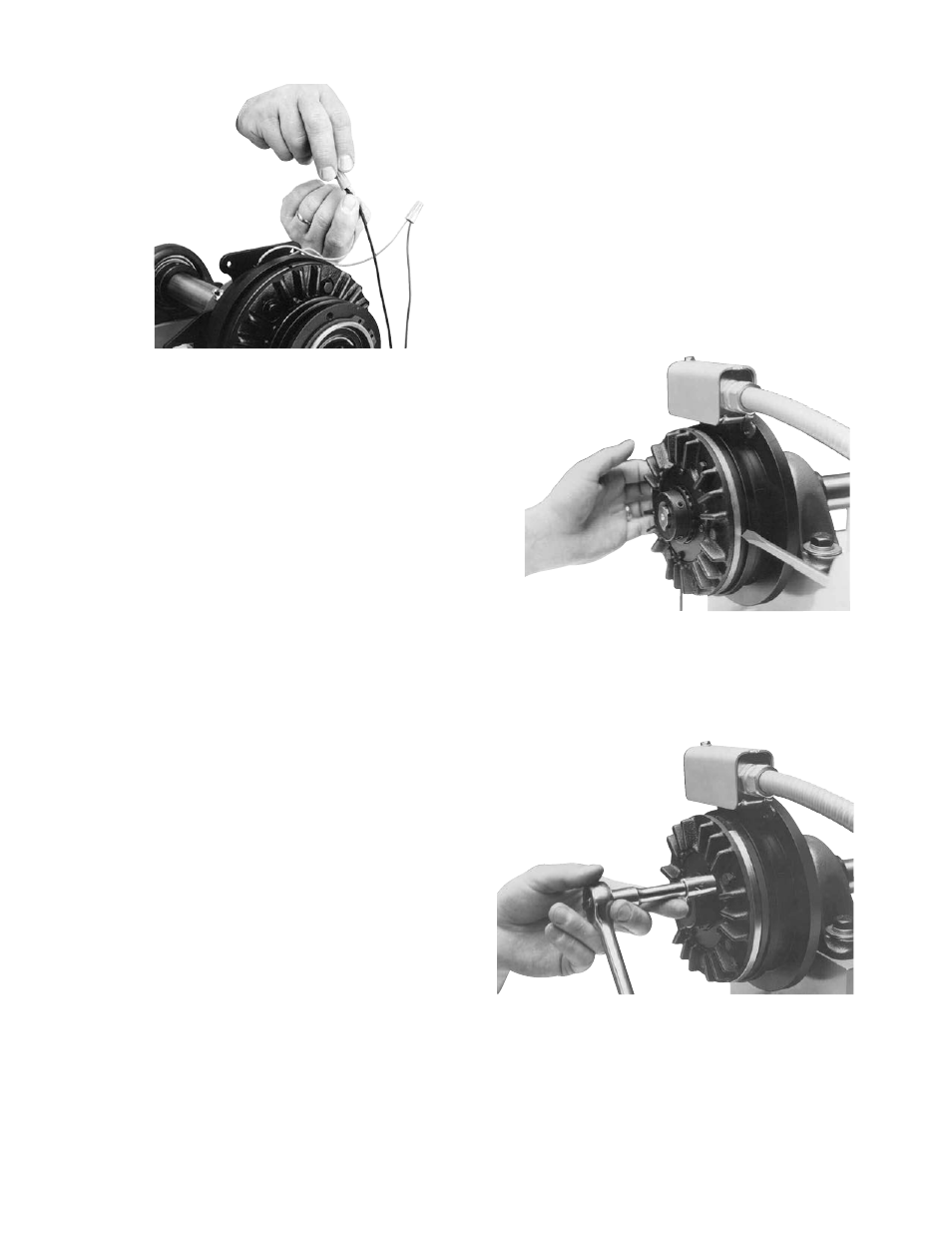
1.
Move the clutch rotor towards the field for disas-
sembly and reassembly. (See Figure 8)
2.
Remove hex head capscrews, washers and lock-
washers to loosen the armature segments from
the cast iron carrier.
(See Figure 9)
Figure 8
Figure 9
4
Warner Electric • 800-234-3369
819-0339
7.
Install the field restraining arm. (See Figure 6)
Note: The field must retain a degree of move-
ment freedom to compensate for bearing and
shaft alignment tolerances.
8. When using a Warner Electric tension con-
trol, follow the connection diagram supplied
with the control. (See Figure 7)
Note: If a Warner Electric TCS-210, -220, -310,
or – 320 control is used, add a 68 ohm, 25 watt
resister or a dummy coil (part no. 275-3843)
across the current sense circuit. Although the
TCS series controls are recommended, a MCS
control can be used with normal hook-up.
9.
Your ATT clutch is now ready for its static test.
Apply DC voltage to the clutch coil through the
clutch control. The armature should pull against
the friction material face.
10. Install the drive belt or chain.
11. Run the clutch under its operating load.
12. Your ATT clutch may not achieve its full torque
until after a short “break-in” period. To break in
the clutch, cycle it on and off under full load at
operating speed a minimum of ten times in quick
Figure 7