Warner Electric Advanced Technology Tension Clutches User Manual
Page 12
12
Warner Electric • 800-234-3369
819-0339
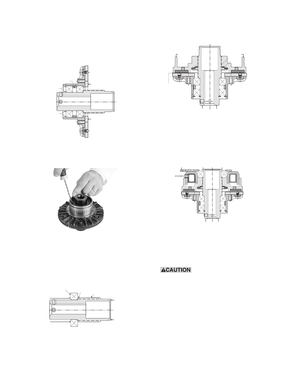
19. Press the outer bearing (Item 5) into place by
applying force evenly against the bearing
outer and inner races simultaneously while
supporting the armature face. Continue pressing
until the outer race firmly locates against the
spacer. (See Figure 44)
20. Install the external and internal retaining rings
(Items 3 and 4) adjacent to the outer bearing.
(See Figure 45)
Note: The Armature Assembly must rotate freely
on the hub. Inspect to insure that the inner bear-
ing is still firmly located against the adapter
shoulder as previously shown in Figure 42. When
inspecting, place unit firmly on flat surface with
exposed hub end up.
21. Install the rotor assembly onto the hub (Item 7)
making sure that the spline teeth are aligned.
(See Figure 46)
22. Press the field assembly onto the hub by
push-
ing the inner race of the bearing while support-
ing on the hub. Apply force until the inner race of
the bearing is located flush against the shoulder
adjacent to the spline. (See Figure 47)
Install the retaining ring (Item 13) on the hub with
snap ring pliers. (See Figure 48)
Rotate the hub. No interference between the
shell and rotor is allowable.
When installing or removing
this or other
retaining rings, be sure to
hold the ring with one hand so it will not
spring away, endangering personnel and
property, should the pliers lose their grip
on the ring. Safety glasses should always
be worn when installing or removing
retaining rings.
Spacer
Support
Support
Press Force
Evenly Applied
Press Force
Evenly Applied
Support
Support
Press
Force
Bearing
Hub
Shoulder
Hub
Press
Force
Support
Maximum
.050 Airgap
All Around
Push
Push
Spline
Detent
Ring
Support
Press
Force
Shell
Assembly
Press
Force
Support
Support
Figure 44
Figure 45
Figure 41
Figure 46
Figure 47