Warner Electric Advanced Technology Tension Clutches User Manual
Page 11
11
Warner Electric • 800-234-3369
819-0339
Note: It is imperative that all bearings be
installed exactly as instructed to avoid damage
to the bearings.
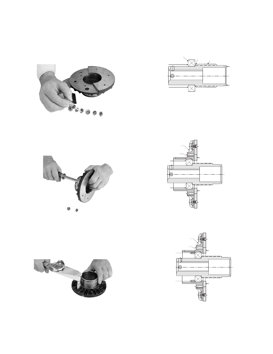
Apply one drop of Loctite grade AA or equivalent
to each capscrew prior to installation.
(See Figure 38)
Install the new armature segments (Item 9-1)
supplied in the kit onto the armature hub, (Item 2)
using capscrews and washers (Items 9-2, and 9-
3). (See Figure 39)
Tighten the capscrews (See Figure 40) to the
appropriate torque for your size unit:
Size
Torque
25
29-35 in.-lbs.
55-115
60-84 in.-lbs.
16. Install the inner adapter bearing (Item 5) onto the
hub, (Item 7)
by pressing on the inner race of
the bearing. With the end of the hub supported
as shown in Figure 41, press the bearing until its
inner race locates against the hub shoulder.
17. Press the hub and bearing into the Adapter
Assembly until the outer race of the bearing
locates against the shoulder of the adapter hub.
Note that the
force is to be exerted on the
outer race. Support the armature face as shown
in Figure 42.
18. Install the spacer (Item 6) as shown in Figure 43.
Support
Support
Press
Force
Bearing
Hub
Shoulder
Hub
Press
Force
Armature
Assembly
Support
Support
Adapter
Shoulder
Press Force
Press Force
Armature
Assembly
Support
Support
Adapter
Shoulder
Spacer
Spacer
Figure 38
Figure 39
Figure 42
Figure 41
Figure 43
Figure 40