Warner Electric Advanced Technology Tension Clutches User Manual
Page 2
2
Warner Electric • 800-234-3369
819-0339
Clutch Installation
1.
Remove your ATT Clutch from its shipping carton
and inspect it thoroughly to ensure that it has
arrived in good condition.
An accessory kit included with your clutch con-
tains a key, retaining ring, and coil wire retainer.
In addition, you may have ordered the optional
sheave or timing belt pulley and field restraining
strap.
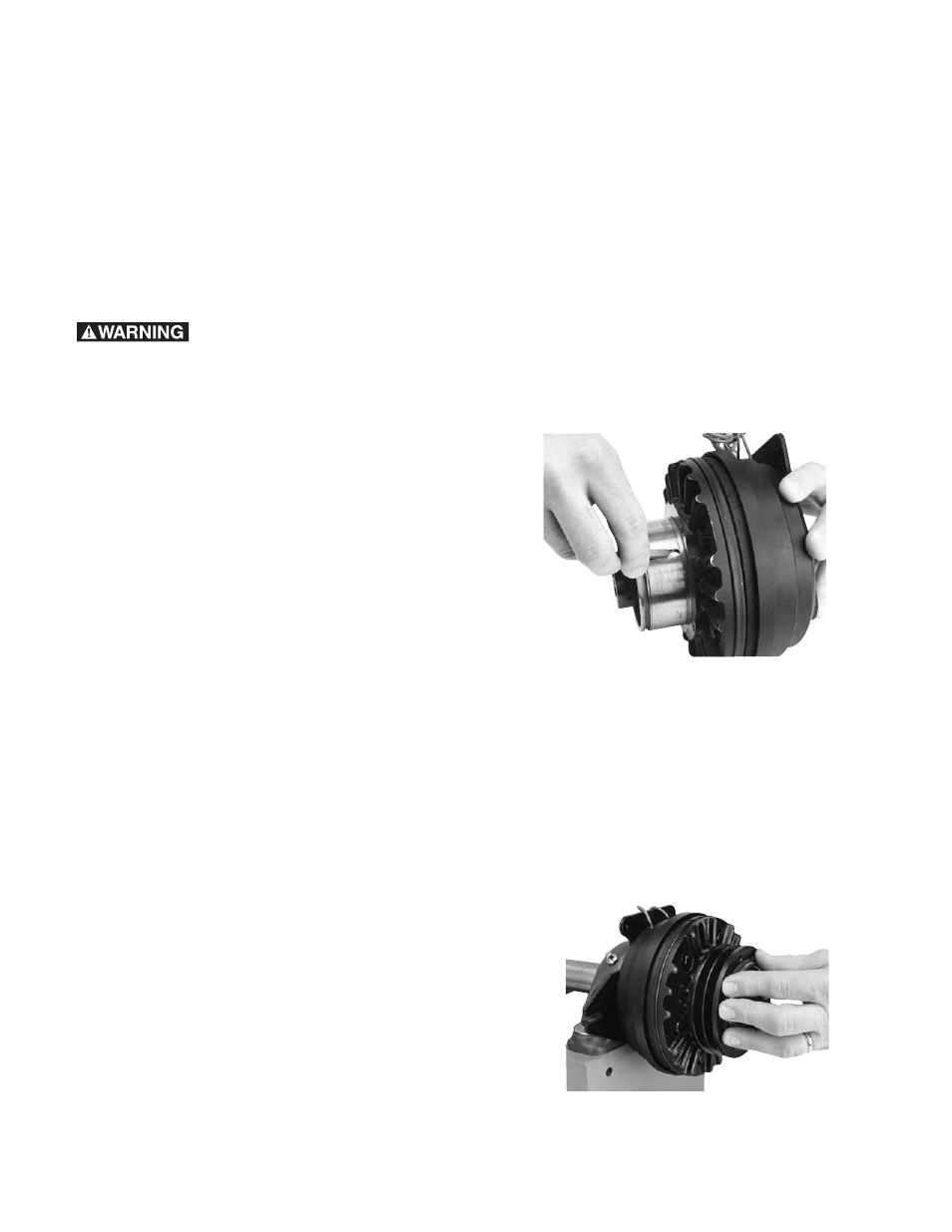
2.
Install the factory-ordered sheave or pulley by
first inserting the key in its keyway. Place the
sheave or pulley so it will fit onto the hub, align-
ing the keyway with the key and keeping the
sheave tapped holes facing away from the
clutch. (See Figure 1)
Gently tap the sheave or pulley until it seats
against the hub shoulder.
Note: Do not force the pulley or sheave onto the
hub if it will not go. Check alignment to assure it
is going on evenly. Customer furnished sheaves,
pulleys and sprockets must be machined per
instructions found on page 16 of this manual
prior to installation. After machining, install per
The Warner Electric Advanced Technology Tension
(ATT) clutch you have purchased has been designed
to provide long and trouble-free service. It is a
rugged and durable unit that is rebuildable with both
friction face replacement and complete clutch rebuild
kits discussed in this service manual. The friction
face replacement kit renews the friction surfaces,
while the complete clutch rebuild kit includes new
bearings, components and hardware in addition to
the friction faces.
This service manual includes instructions required for
installation, repair on the shaft, and major rebuilding,
as well as troubleshooting information, specifications,
dimensions, an exploded view and parts list. Please
refer to the Table of Contents above for the section
page numbers.
All installation and repair involving clutches must be
carried out in accordance with the procedures speci-
fied in the service manual. All stated or implied man-
ufacturer warranties are voided if this product is not
installed and serviced in accordance with these
instructions.
Contents
Installation . . . . . . . . . . . . . . . . . . . . . . . . . . . . . . . . . 2
Clutch Repair – On the Shaft . . . . . . . . . . . . . . . . . . 4
Clutch Service – Major . . . . . . . . . . . . . . . . . . . . . . . 7
Troubleshooting. . . . . . . . . . . . . . . . . . . . . . . . . . . . 15
Dimensions . . . . . . . . . . . . . . . . . . . . . . . . . . . . . . . 16
Specifications . . . . . . . . . . . . . . . . . . . . . . . . . . . . . 16
Exploded View and Parts List. . . . . . . . . . . . . . . . . 18
Warranty . . . . . . . . . . . . . . . . . . . . . . . . . . Back Page
Failure to follow these
instructions may result in product damage, equip-
ment damage, and serious or fatal injury to per-
sonnel.
Figure 1
Figure 2