Warner Electric PCBC-500 Clutch_Brake Coupling User Manual
Page 9
Warner Electric • 800-825-9050
819-0484
9
PCC-500 Clutch Coupling
Normal Duty Pin Drive Armature
The illustration drawing, parts list, and exploded view for
this unit can be found on pages 26 and 27.
Either the magnet half of the clutch unit or the
armature half of the unit may be mounted on the
shaft first, depending on the characteristics of each
application.
A. Assembling the Magnet and Magnet
Hub
1. Determine which side of the magnet hub will be
mounted to the magnet. The hub is
reversible. The side to be used will depend on
which side the taperlock bushing is to enter.
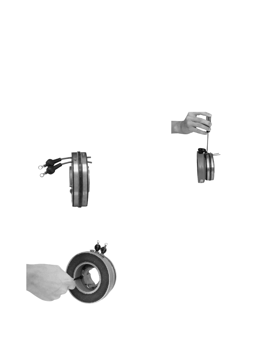
2. Insert the lead wires through the rubber
terminal caps and into the collector ring. The
wires should be inserted from the same side
of the ring that the magnet will be mounted on.
(Figure 1)
3. Mount the magnet to the magnet hub using
capscrews and lockwashers. (Figure 2)
Figure 1
4. Secure the lead wires to the magnet
terminals with screws and lockwashers.
5. Pull the rubber terminal caps over the
terminals.
6. Pull the excess lead wire length from the back-
side of the collector ring (away from the mag-
net) until the wire is snug.
7. Tighten down the screw in the collector ring.
The shaft cone point on the screw should
pierce the lead wire insulation to make a good
electrical contact. The head of the screw should
be below the surface of the collector ring.
(Figure 3)
8. Cut off the excess wire.
B. Mounting the Magnet and Magnet Hub
The magnet and magnet hub are mounted on the shaft
with a taperlock bushing. All parts must be clean and
free from burrs and chips before
assembling.
1. Place the bushing into the hub and insert the
key. The key is a side-to-side fit and should not
contact the top of the keyway.
2. Insert the locking setscrews loosely into the
bushing and slide the assembly onto the shaft.
3. If the armature has been secured to the shaft
first, then adjust the magnet's position to allow
approximately 1/32-inch between the two
faces. (Figure 10)
4. Secure the magnet's position on the shaft by
alternately tightening each setscrew with a
torque wrench to 175 in. lbs. torque. During the
tightening process the bushing should be
tapped lightly to make certain it seats-in
properly.
Figure 2
Figure 3