Warner Electric PCBC-500 Clutch_Brake Coupling User Manual
Page 7
7
Warner Electric • 800-825-9050
819-0484
PCC-500 Clutch-Coupling
Heavy Duty Spline Drive Armature
The illustration drawings, parts list, and exploded view
for this unit can be found on pages 28 and 29.
Either the magnet half of the clutch unit or the
armature half of the unit may be mounted on the shaft
first, depending on the characteristics of each
application. (Figure 4)
A. Assembling the Magnet and Magnet
Hub
1. Determine which side of the magnet hub will be
mounted to the magnet. The hub is reversible.
The side to be used will depend on which side
the taperlock bushing is to enter.
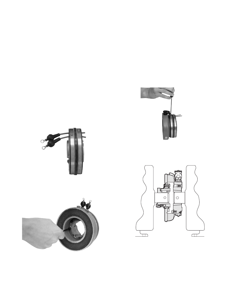
2. Insert the lead wires through the rubber
terminal caps and into the collector ring. The
wires should be inserted from the same side
of the ring that the magnet will be mounted on.
(Figure 1)
3. Mount the magnet to the magnet hub using
capscrews and lockwashers. (Figure 2)
Figure 1
4. Secure the lead wires to the magnet
terminals with screws and lockwashers.
5. Pull the rubber terminal caps over the
terminals.
6. Pull the excess lead wire length from the back-
side of the collector ring (away from the mag-
net) until the wire is snug.
7. Tighten down the screw in the collector ring.
The sharp cone point on the screw should
pierce the lead wire insulation to make a good
electrical contact. The head of the screw should
be below the surface of the collector ring.
(Figure 3)
8. Cut off the excess wire.
Figure 2
Figure 3
Figure 4 - PCC Clutch Coupling