Warner Electric PCBC-500 Clutch_Brake Coupling User Manual
Page 12
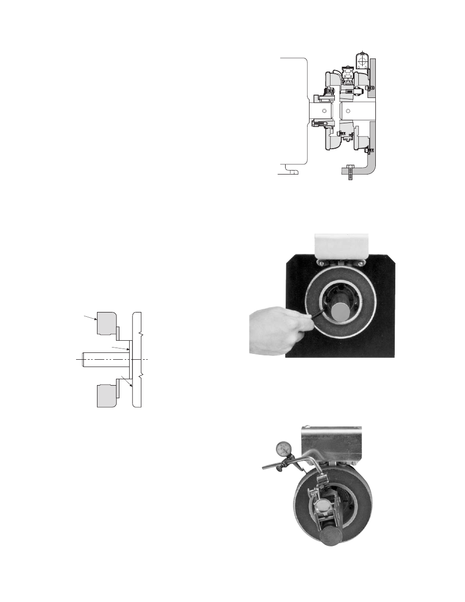
PCBC-500 Heavy Duty Spline Drive
Armature Clutch/Brake Coupling (Figure 2)
The illustration drawing, parts list, and exploded view for
this unit can be found on pages 32 and 33.
A. Installing the Conduit Box
Install the conduit box on the magnet. Instructions for
this procedure can be found on page 20.
B. Mounting the Magnet
The brake half of the clutch/brake unit is usually installed
first; however, in some cases it may be
necessary to start with the clutch portion of the unit
to assure a proper assembly when complete.
The brake magnet is mounted to a stationary machine
member by a flange. Extreme care must be taken in
se lect ing the location for the mounting of the magnet.
Proper positioning is very important for the unit to
function correctly.
1. A pilot diameter on the mounting surface is
essential to hold the magnet within the required
tolerances. (Figure 1) Also see “Customer Shall
Maintain” on page 32.
2. A machined pilot diameter is provided on the
magnet mounting flange (refer to illustration
drawings on page 32) to aid in the proper
positioning of the magnet.
Field
Pilot Diameter
Mounting Surface
Figure 1
3. Once the mounting surface has been
prepared, the magnet is bolted in place with
capscrews and lock-washers. (Figure 3)
4. Use a dial indicator to check the unit for
concentricity and squareness to the shaft.
The unit should be concentric within .010 T.I.R.
and square within .006 T.I.R.
(Figure 4)
Figure 3
Figure 4
Figure 2 - PCBC Clutch/Brake Coupling
Warner Electric • 800-825-9050
819-0484
12