Warner Electric PCBC-500 Clutch_Brake Coupling User Manual
Page 20
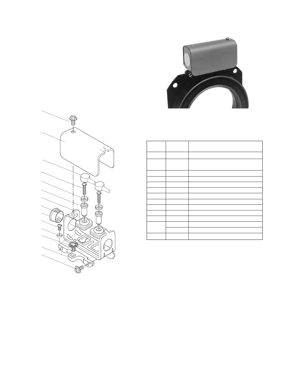
Installation Instructions
Conduit Box Kit No. 5200-101-010
Description
This Warner Electric conduit box is designed to
provide a proper means for field wiring terminations. It
conforms to the requirements of Underwriters
Laboratories. Kit No. 5200-101-010, plus magnet
terminal accessory kit, contains all components
needed to assemble a conduit box for the above
mentioned units. Please follow these instructions
carefully when installing this conduit box. Failure to
comply with these instructions could result in unsafe
electrical con nec tions
.
Parts List for Kit 5200-101-010
Item
Quan.
Part Name
1
1
Bracket
2
1
Screw, Hex, Washer Hd.
and Sems Conical Washer
3
1
Box, Conduit
4
3
Screw, Hex. Washer Hd.
5
1
Plug, Protective
6
2
Grommet, Wire
7
2
Spacer, Terminal
8
2
Cap, Terminal
9
1
Screw, Hex. Washer Hd.
9-1
1
Terminal, Ring
10
1
Cover Assembly
*11
2
Screw No. 6 Brass
2
Screw No. 8 Brass
†12
2
Terminal, Ring
* The No. 6 screws are required on Sizes 375, 400, and 475. All
others use No. 8.
† Terminal Ring provided with terminal accessory kit 5311-101-003,
5311-101-001 respectively, supplied with magnets.
Note: All mounting screws are self-tapping.
4
10
8
11
12
7
3
6
5
9
9-1
2
1
4
Warner Electric • 800-825-9050
819-0484
20