Warner Electric EUM-50_EUM-100_EUM-180_EUM-210_EUM-215 User Manual
Page 4
4
Warner Electric • 800-825-9050
P-226 • 819-0355
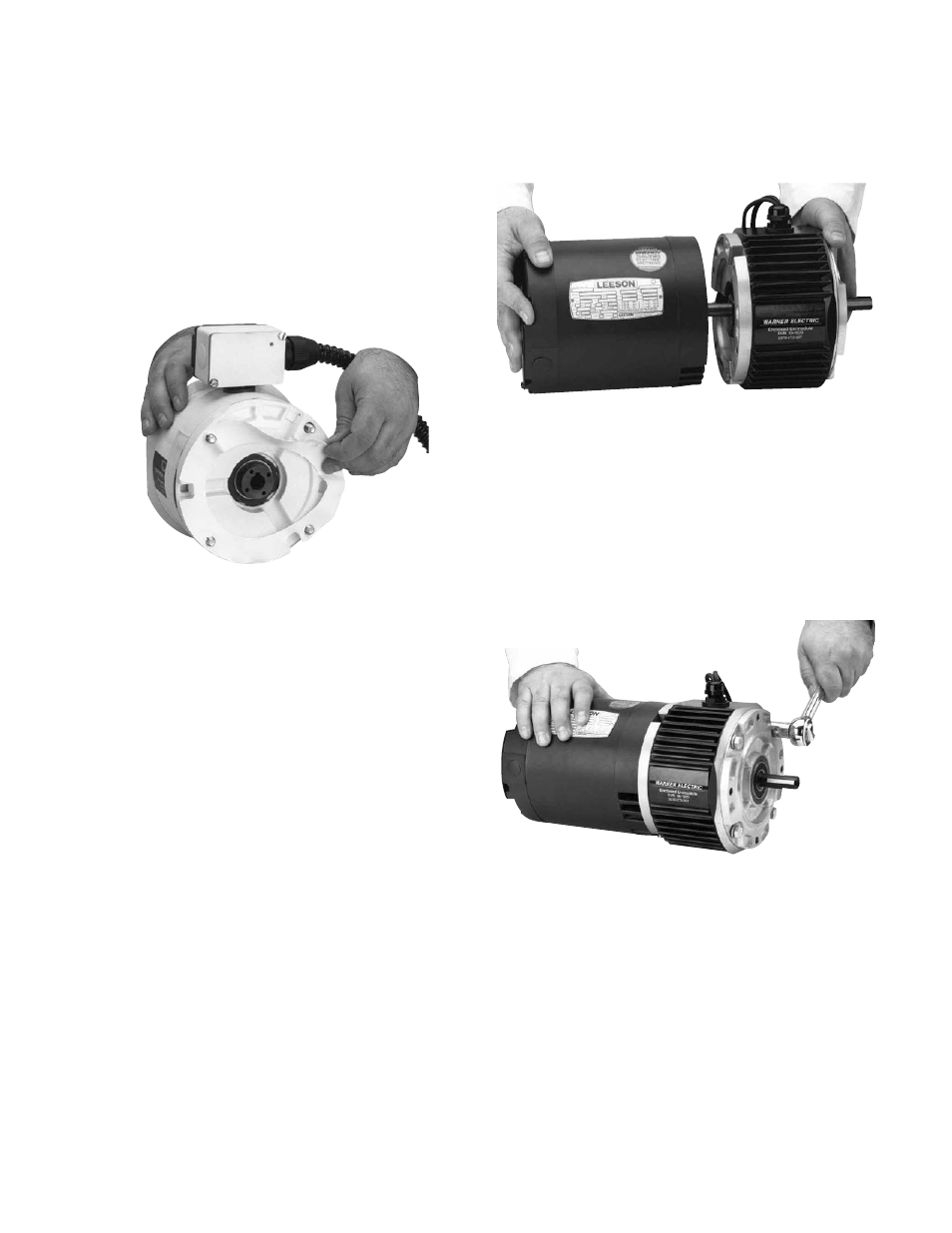
B. For All UniModule Models
Note: The 1020 UniModule is furnished with
a special key already assembled in the rotor
hub. Do not use another key!
1. Before sliding UniModule onto motor, align
set screws on rotor input hub to access
slots on clutch side of module. Insert into a
set screw and slide assembly onto motor
shaft as shown in Figure 2. Align key in
UniModule with motor shaft keyway.
Figure 2
Do not use force. If UniModule does not
slide on freely, polish motor shaft sufficiently
to achieve a slip fit.
Note: Sizes 100, 210 and 215 UniModules
require an adapter ring to be mounted to
the motor prior to mounting the 1020
UniModule. Adapter and mounting
hardware are provided with the
UniModule assembly.
Step2:
A. For UniModule Models Other Than
Washdown
1. Insert four large capscrews with lock
washers provided through mounting holes in
housing and into tapped holes on motor
face. Tighten alternately and securely to 30
to 35 ft. lbs. torque. See Figure 3.
B. For Washdown Models Only
1. Insert four large capscrews provided
through the large plastic washers and
through mounting holes in housing and into
tapped holes on motor face. Tighten
alternately and securely to 30 to 35 ft. lbs.
torque. See Figure 3.
Figure 3
Step3:
A. For All UniModule Models
1. Tighten both set screws on the module
input hub with prepositioned Allen wrench
alternately and securely to 80 to 85 in. lbs.
for all sizes. See Figure 4.
Figure 4
B. For Washdown Models Only
1. After tightening set screws on the rotor
input hub, Figure 3, use plastic screws
provided in the kit to plug threaded holes
and position rubber seal to cover all slots.
Step4: Mounting to a Reducer
The output side of a UniModule may be mounted
directly to a reducer.