Warner Electric EUM-50_EUM-100_EUM-180_EUM-210_EUM-215 User Manual
Page 3
3
Warner Electric • 800-825-9050
P-226 • 819-0355
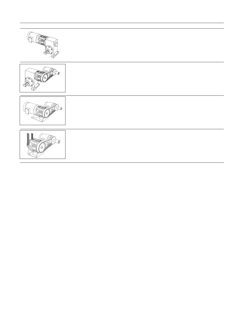
FortheseEUMcombinations:
Usetheseinstallationsteps:
Enclosed UniModule Clutch-Brake Between
C-Face Motor and Reducer – 1020
1, 2, 3, 4, 7
Enclosed UniModule Clutch-Brake – 2030
4, 7
Motor Mount Enclosed UniModule Clutch-Brake
On C-Face Motor – 1020-M
1, 2, 3, 6, 7
Base-Mounted
Enclosed UniModule Clutch-Brake – 2030-B
5, 7
InstallationInstructions
Warner Electric’s Enclosed UniModule has been
designed to NEMA standards and can be
installed with all standard power transmission
drive systems. Before installing the Enclosed
UniModule to a motor or reducer, make certain
that the EUM size and NEMA frame dimensions
match according to the chart.
Install your specific modular combination
according to the installation steps specified in
the table on page 2. Use only those steps
indicated for each combination.
Note:The equipment covered by this service
manual must be installed in accordance with
these instructions. Failure to do so may
damage the equipment and void the warranty.
Note: Special plugs and plastic screws are
provided with each washdown kit. All unused
holes are to be plugged to prevent debris
buildup and to ensure that the clutch/brake
stays dry.
MountingToAMotor
Step1:
A. For Washdown Models Only:
1. Slip rubber shield (seal) over clutch and end
of module; exact position of rubber band is
described in step 3.B. Place gasket
between motor and clutch end; be sure to
select correct gasket to match clutch end.