Warner Electric Electro-Module EM-50, EM-100, EM-180, EM-210, EM-215 User Manual
Page 7
7
Warner Electric • 800-825-9050
P-213 • 819-0303
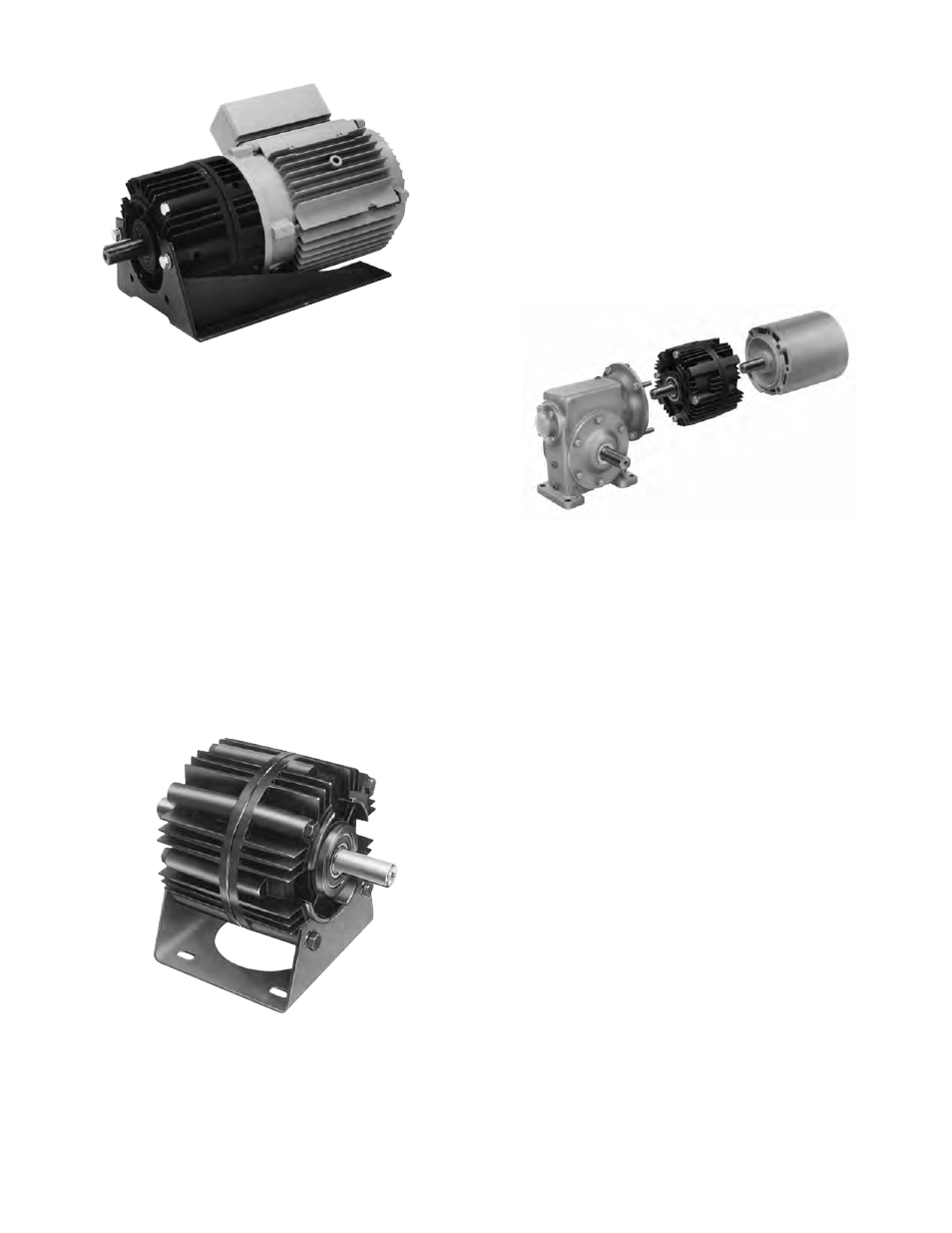
Figure 11
3. Secure the Motor Mount in place with two (2)
longer mounting bolts and the two shorter
bolts all provided in the kit.
Section F: Installing the Base Mount
Modules 20-30 and 30-40 can be base-mounted.
1. Mount the modules so that the base is located
below the ventilation holes. A pilot diameter
on the end of each module mates with pilot
diameters on the base.
2. Secure the base to the modules with the four
(4) bolts provided. (Figure 12)
Figure 12
Section G: Mounting to a Reducer
The output side of a brake (20) or output clutch
(40) module may be mounted directly to a reducer.
1. Align the output shaft and key of the modules
with the corresponding shaft hole and keyway
of the reducer. Slide the assembly together,
matching the pilot diameter on the module with
a pilot diameter on the reducer. (Figure 13)
Figure 13
2. Bolt the module to the reducer flange. The
four (4) bolts required (3/8 - 16 UNC-2A) are
normally furnished with the reducer.
Section H: Electrical Connections
The conduit connection hole in the motor clutch
module (10), brake (20), and input clutch (30) are
threaded for standard conduit connectors. The
wiring diagram, included with each Warner Electric
control shows the proper electrical connections
that must be made. (Control Service Manual P-239
includes complete information on all standard
control power supplies.)
For clutch/brake combinations, connect the red
wire from one module and the black wire from the
other module to the same terminal of the DC sup-
ply. With most basic Warner Electric controls, one
terminal is normally used for two connections –
one from the brake and one from the clutch.
For wiring of clutches, brakes, and clutch/brake
combinations consult manual P-239 for the wiring
diagram of the control being used. These
clutch/brakes are not polarity sensitive.