Warner Electric Electro-Module EM-50, EM-100, EM-180, EM-210, EM-215 User Manual
Page 5
5
Warner Electric • 800-825-9050
P-213 • 819-0303
Section B: Bolting Two Modules Together
The brake module (20) and/or output clutch
module (40) may be assembled to the mounted
motor clutch module (10) or the input clutch (30).
1. Position the modules so that, in the usual
horizontal position, the ventilation holes are
down to prevent foreign matter from falling
into the units.
2. Bolt the modules together with the long hex
head bolts that are provided, see figure 5.
Mating pilot diameters assure proper align-
ment between module assemblies.
3. Proceed to Section C
Figure 5
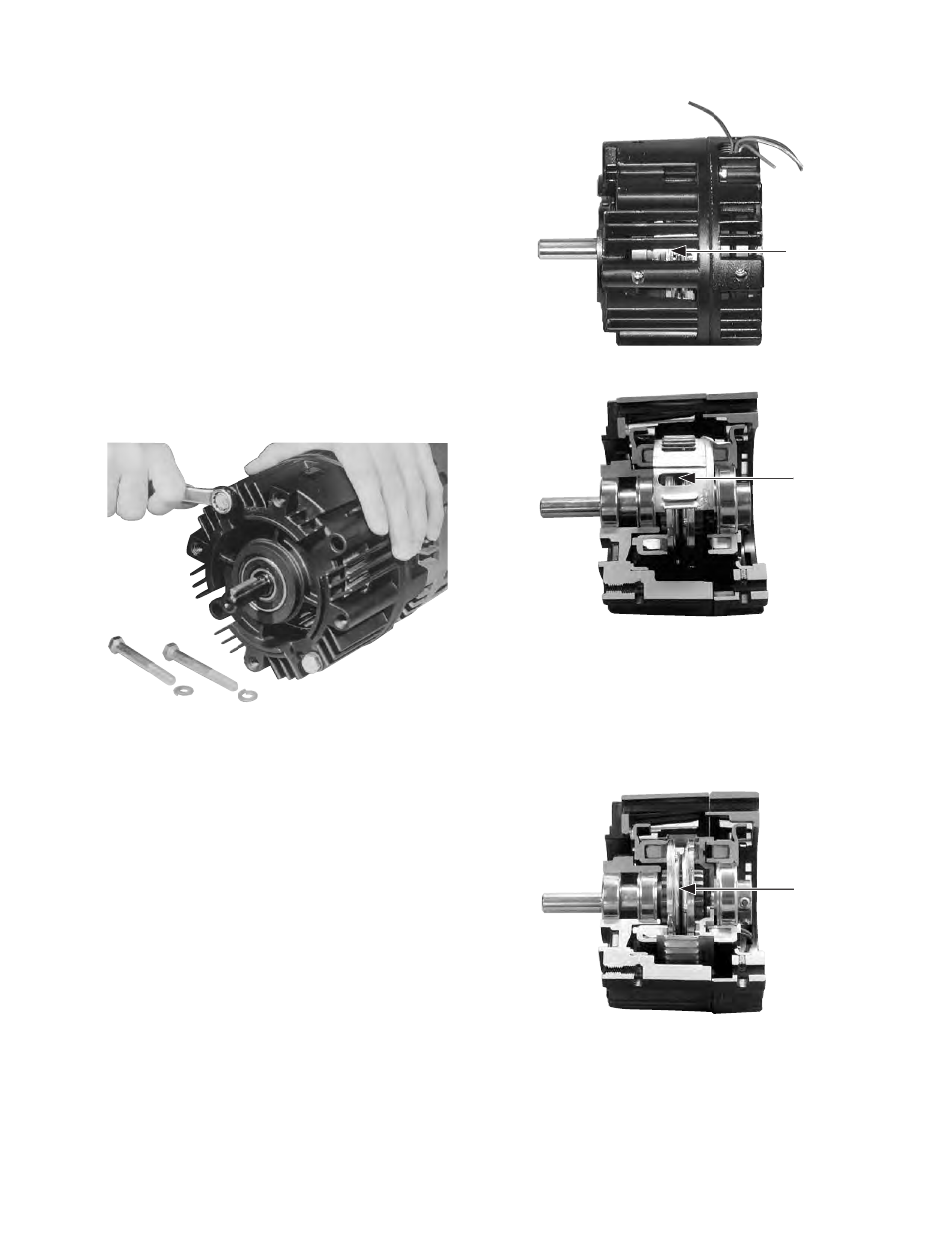
Section C: Adjusting Airgap
For new installations it is necessary to adjust the
airgap between the friction faces of the clutch
and/or brake.
To set the airgap for an Electro-Module (EM) you
will need to access the armatures. On an EM
there are gaps between the fins on the housing
on 1/2 of the unit circumference. When looking
through this gap, you will see the fan on the
clutch rotor. In that fan there is a 1/2 x 1 inch
window. It is possible to look inside the unit and
see the armatures by looking through this win-
dow. When looking through this window you will
be looking between the two armatures of a
clutch/brake unit as shown in figures 6 and 7.
Figure 6
Figure 7
If the armature for either the clutch or the brake
is too far away from its mating friction surface, it
is possible to move this back into adjustment
using a flat blade screwdriver between the two
armatures. See figure 8.
Figure 8