30 input clutch module – Warner Electric Electro-Module EM-50, EM-100, EM-180, EM-210, EM-215 User Manual
Page 14
14
Warner Electric • 800-825-9050
P-213 • 819-0303
30 Input Clutch Module
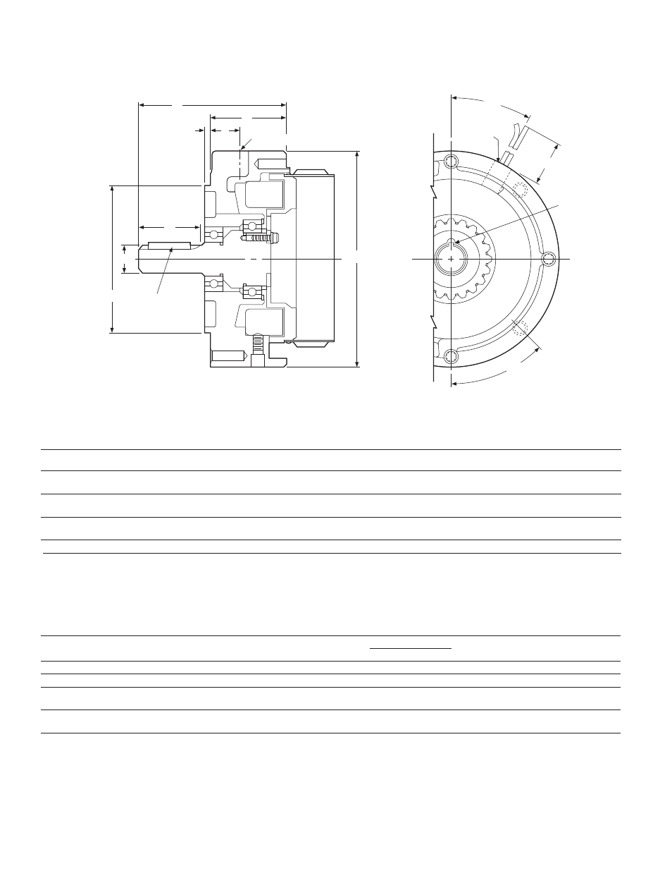
All dimensions are nominal, unless otherwise noted.
Size
A
B
C
D
E
F
G
I
AA
BB
CC
DD`
Max.
Min.
Pilot Dia.
Dia.
Max.
H
Dia.
Min.
Key
50
1.000
1.56
3/16 x
1.813
4.500
.625
4.328
2.266
6.688
30°
36
45°
3/16 x 3/16
3/16 x 1-3/8
100
1.000
1.56
3/16 x
1.813
4.500
.625
4.328
2.266
6.688
30°
36
45°
3/16 x 3/16
3/16 x 1-3/8
180
1.000
1.56
3/16 x
1.891
4.500
.875
4.391
2.266
6.688
30°
36
45°
3/16 x 3/16
3/16 x 1-3/8
210
1.500
.312
1/4 x 1/4
2.500
8.500
1.125
5.391
2.438
9.219
25°
36
45°
1/4 x 1/4
Specifications
Inertia–WR
2
(lb. ft.)
Model Size
Voltage DC
Static Torque (lb. ft.)
Max. RPM
Rotor
Shaft
Weight (lbs)
NEMA Frame Size
50
6, 24, 90
16
3600
.020
.001
6.4
56C/48Y*
100
6, 24, 90
30
3600
.046
.002
8.4
56C/48Y**
180
6, 24, 90
30
3600
.046
.002
8.4
182C/143TC
184C/145TC
210
6, 24, 90
95
3600
.188
.017
19.8
213C/182TC
215C/184TC
Typical End View
AA
BB
CC
DD
1/2" NPT
G
A
B
H
D
E
F
C
Electrical Connection
I
* For 56C/48Y Frame motors 3/4 HP and smaller the EM-100 size
may be used where extended life is desirable.
** EM-100 size is recommended for motors 1 HP and larger.
For NEMA standard frame sizes, see page 20.
50-30
100-30
180-30
210-30