Warner Electric Electro-Module EM-50, EM-100, EM-180, EM-210, EM-215 User Manual
Page 19
19
Warner Electric • 800-825-9050
P-213 • 819-0303
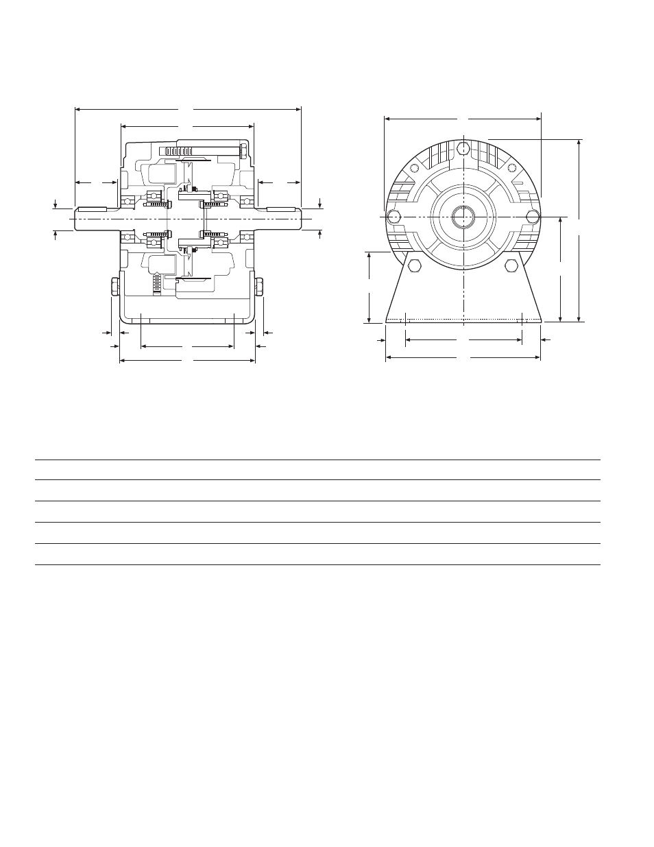
EM-30/40 Input Clutch/Output Clutch Combination
EM-30/40 Input Clutch/Output Clutch Combination – Base Mounted
All dimensions are nominal, unless otherwise noted.
Size
A
B
C Min.
D
E
F
G
H
I
J
K
L
M
N
O
50
5.719
9.516
1.813
.625
5.672
.844
4.000
.344
6.688
3.500
6.844
2.000
6.000
.500
5.000
100
5.719
9.516
1.813
.625
5.672
.844
4.000
.344
6.688
3.500
6.844
2.000
6.000
.500
5.000
180
5.719
9.656
1.891
.875
5.672
.844
4.000
.344
6.688
4.500
7.844
3.000
6.625
.813
5.000
210
7.719
12.969
2.500
1.125
8.203
1.094
6.000
.438
9.688
5.250
9.906
3.375
9.000
.625
7.750
B
A
D
C
F
G
E
H
H
F
C
D
30
Input Clutch
Module
40
Output
Clutch
M
O
N
N
J
K
L
I
Note: Mounting base is optional and is ordered separately.
Input Clutch (30) module and Output Clutch (40) are
ordered separately.
Electro-Modules are individual clutch or brake
units which are assembled together to comprise
a clutch, a brake or a clutch/brake combination.
Electro-Modules are designed for use with C-
face motors and reducers. Some versions can
be base mounted as well.
Prior to assembly ensure that the components
you have will create the unit you need.
The 10 Motor Clutch Module is designed to
mount on the face of the NEMA C-Face motor.
The rotor assembly has a hollow bore and is
mounted onto the shaft of the motor. The 10
Module cannot be used alone, it must be used
with either the 40 Module to create a clutch
combination or a 20 Module to create a
clutch/brake combination.