Warner Electric Electro-Module EM-50, EM-100, EM-180, EM-210, EM-215 User Manual
Page 6
6
Warner Electric • 800-825-9050
P-213 • 819-0303
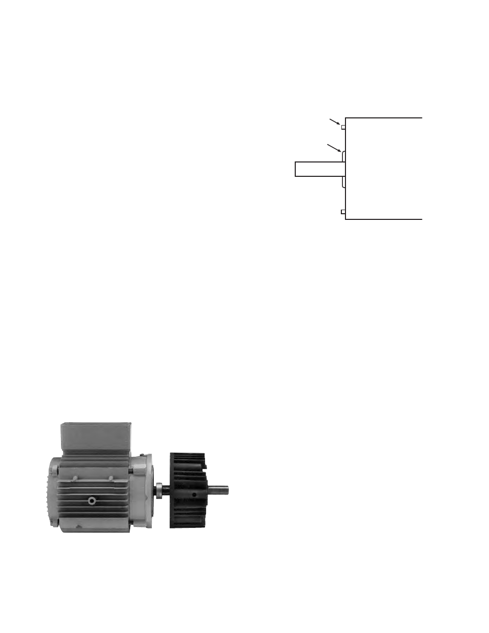
3. When using the EM-180-20 a possible inter-
ference may exist between the splined arma-
ture hub and some motors. (See Figure 10) A
spacer ring is provided with the EM-180
mounting accessory to provide the necessary
running clearance.
Figure 10
Place the spacer ring between the brake
module housing and the C-face of the motor
when bolting the two units together.
4. Align the motor shaft and key with the mating
shaft hole and key slot in the brake module.
5. Secure brake module to the motor C-face with
the four (4) long 3/8-inch hex head capscrews.
Section E: Installing the Motor Mount (M)
A Motor Mount (M) can be installed to the brake
or output clutch module to provide a foot mount-
ing for the complete assembly of module and
motor.
1. Remove the two (2) long hex head bolts from
the side of the module toward the ventilation
holes.
2. Mount the module on the Motor Mount so that
the base of the Motor Mount is underneath
the modules and motor. (See Figure 11) A pilot
diameter on the module mates with a pilot
diameter on the Motor Mount.
This is a three step process.
1. Simply slide the screwdriver through the
window and press the armature toward its mat-
ing friction surface.
2. Rotate the output of the unit. The rotor and the
window should stay in place when you do this.
Only the armatures will move. Rotating the
rotor will move the window.
3. Repeat steps 1 & 2 to ensure that the airgap
between armature and its mating friction sur-
face is about 1/32” and that the armature is
kept square. (If the armature is cocked, it may
engage on one rim, giving the appearance of
engagement but failing to provide full torque.)
Section D: Mounting the Brake to a Motor
The brake module (20) can be mounted directly
to a motor.
1. Insert a key in the motor shaft keyway. Prick
punch the end of the (EM-50 and EM-100)
motor shaft keyway to prevent the key from
sliding out.
2. A set collar is provided in the EM-180 and
EM-210 mounting accessory to prevent the
key from sliding out. Slide the set collar up
against the motor bearing and tighten the
setscrew securely. (Figure 9)
Figure 9
C-face mounting
If this boss extends
beyond the C-face
surface use the
spacer.
Do not use spacer
if boss is below the
C-face surface.