Vestil EPT-30 User Manual
Page 11
11
Curtis PMC 1207/1207A Manual
4
the user-adjustable potentiometers. Access is also needed to plug the programmer
into the connector beneath the sliding cover, and to view the Status LED.
Although not usually necessary, a thermal joint compound can be used to
improve heat conduction from the case to the mounting surface.
CONNECTIONS:
Low Current
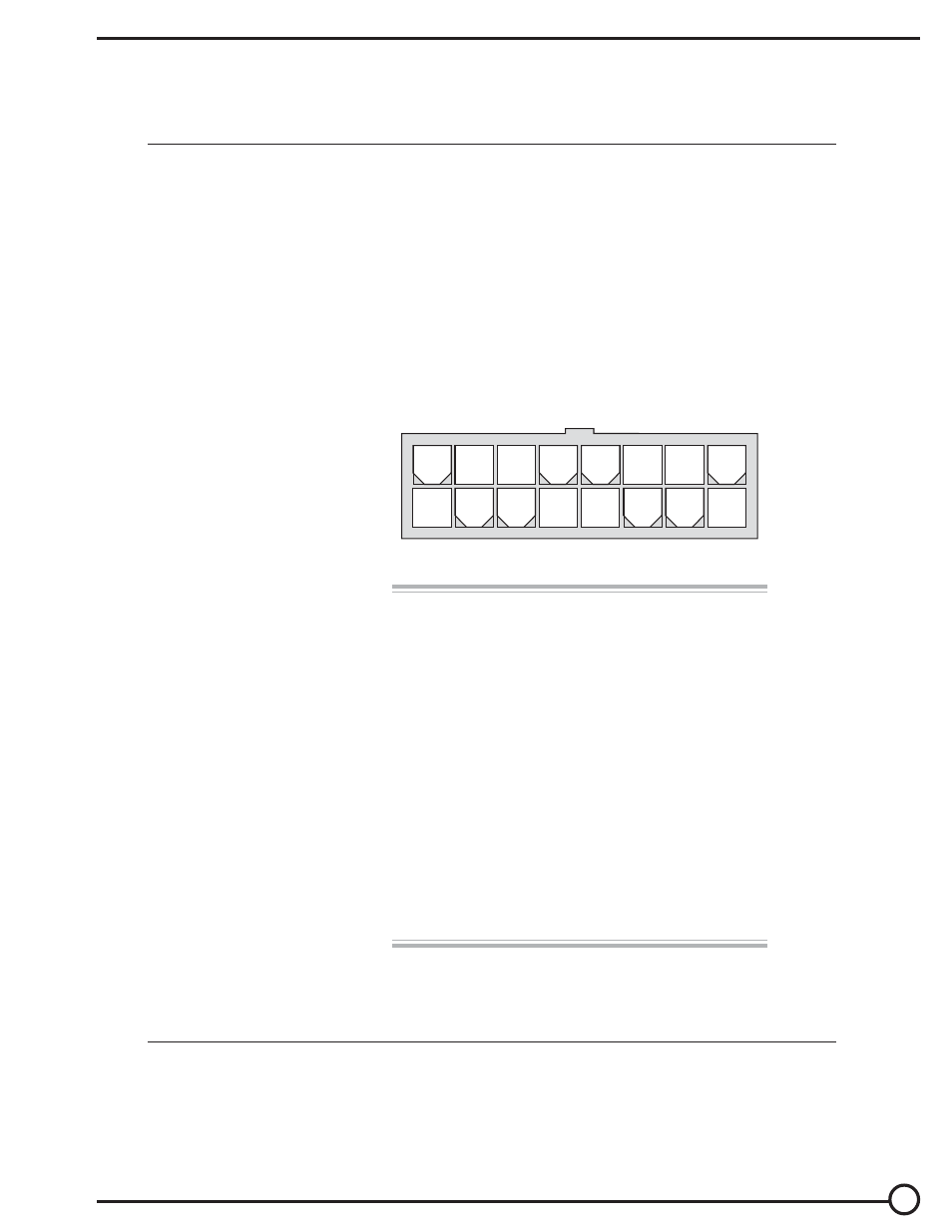
An integrated 16-pin low power connector molded into the front of the control-
ler provides the low power logic control connections (see pin list below). The
mating connector is Molex Mini-Fit Jr., part number (5557) 39-01-2165.
Contact Molex regarding compatible pins for various wire sizes.
2 — INSTALLATION & WIRING: 1207 Controller
Pin 1
shunt field driver output; n/c for series motors
Pin 2
reverse contactor driver output
Pin 3
forward contactor driver output
Pin 4
main contactor driver output
Pin 5
throttle: 3-wire pot high
Pin 6
throttle: 3-wire pot wiper or 0–5V
Pin 7
throttle: pot low
Pin 8
throttle: 2-wire 5k
Ω–0 or 0–5kΩ input
Pin 9
throttle: 0–10V
Pin 10
emergency reverse (BB) check output [optional]
Pin 11
reverse input
Pin 12
forward input
Pin 13
emergency reverse input
Pin 14
mode selection input
Pin 15
brake input
Pin 16
keyswitch input (KSI)
16
15
14
13
12
11
10
9
8
7
6
5
4
3
2
1