Connecting network devices, Wiring recommendations, Application diagram – Staub Electronics AN-100-SERIES ARAKNIS - 100-SERIES 8-PORT UNMANAGED GIGABIT SWITCH WITH REAR PORTS User Manual
Page 16: Connection instructions, Connecting network, Devices, 1 wiring recommendations, 2 application diagram, 3 connection instructions, Table 3
© 2013 Araknis Networks
®
16
3. CONNECTING NETWORK DEVICES
3.1 —
Wiring
Recommendations
3.2. —
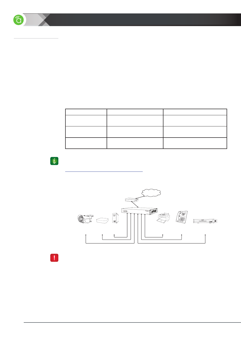
Application Diagram
3.3 —
Connection
Instructions
Setup of the AN-100-SW-R is very simple and requires nothing more than connections
to other equipment and power. This switch provides automatic crossover detection
functionality for any port, so connections can be made to other switches without the need
for a crossover cable between devices.
Make all Ethernet connections using twisted-pair, 568B-terminated straight-through cables
manufactured and terminated to meet the Cat5e/6/+ standard in use for the installation.
Patch cables may be stranded. Bulk wire should be solid core to permit the longest run
possible. No cable length should be over 100 meters in total, containing a maximum of 10
meters of stranded patch cables. It is highly recommended to test every cable in use with
a network analyzer prior to finalizing the installation.
Item
Description
Max Length (If applicable)
Bulk Wire
Solid Core, EIA/TIA certified
Cat5e or better
100 meters without patch cables;
90 meters with patch cables
Connectors for Wire
RJ45 of the same standard
as the bulk cable in use
---------
Patch Cables
Stranded, EIA/TIA certified
No more than 10 meters of patch
cables to a run in total
1. Install the network switch and any equipment to be connected.
2. Route bulk wire or patch cables between equipment locations.
3. Terminate and test all cables.
4. Connect each cable between the LAN port on the equipment requiring network access
and a port on the switch. Leave one switch port open to allow connection to the rest of
the network.
5. Connect a network cable from the switch to the device providing network connectivity.
6. Power up all equipment and test each attached device for network connectivity.
Router
Araknis Switch
Desktop
PC
IP Camera
Printer/
Scanner
IP Surveillance
NVR
IP Phone
AppleTV
Internet
(Modem)
(external power
supply needed)
(external power
supply needed)
Figure 13.
Application Diagram
Table 3.
Cable and Connector Recommendations
Leave all equipment un-powered while making connections.
Pro Tip: For guaranteed, hassle-free performance, use Binary™ bulk wire, and Wirepath™
cable connectors and manufactured patch cables. All of the items are available at
.