Rear panel – Staub Electronics B-500-MTRX-230-8X16 BINARY - HDMI 8X16 MATRIX SWITCH WITH HDMI AND HDBASET OUTPUTS User Manual
Page 7
B-500-MTRX-230 Installation Manual
Pg. 7
www.snapav.com Support: 866.838.5052
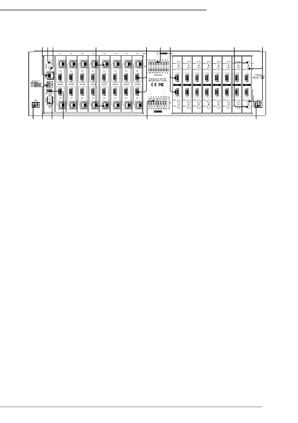
6.2. Rear Panel
1. Ethernet Port
RJ45 port for connecting an Ethernet Cat5e/6 cable for IP control of the B-500-MTRX-230.
2. System All IR Out
3.5mm mono mini port, repeats all IR commands from all connected HDBaseT outputs (from IR Receiver port of
B-500-RX-230-IR).
3. System IR In
3.5mm mono mini IR input port for matrix control.
4. HDBaseT Outputs 1 through 16 (RJ45)
Connect 568B terminated Cat5e/6 HDBaseT cable routed to a B-500-RX-230-IR to feed HDMI signal to display.
Output simultaneously displays the same source as the HDMI output of the same number. Odd numbered outputs
are at the top and even numbered outputs are at the bottom.
5. HDMI Outputs 1 through 16
Connect HDMI cables to route to displays. Output simultaneously displays the same source as the HDBaseT output
of the same number. Odd numbered outputs are at the top and even numbered outputs are at the bottom.
6. Output Number Legend
Printed diagram to indicate output numbering.
7. HDMI Inputs 1 through 8 (or 16)
Connect HDMI cables from sources to the matrix switcher for distribution. Odd numbered outputs are at the top and
even numbered outputs are at the bottom.
8. IR Output to Source 1 through 8 (or 16)
Blue 3.5mm mono mini ports are used to connect IR flashers for controlling sources. These ports may be set to
route commands only from the IR output corresponding to the HDBaseT output number (IR zone routing), or directly
to the source selected on an HDBaseT output (IR source routing). Odd numbered outputs are at the top and even
numbered outputs are at the bottom. See Section 9.1. IR Source Routing on page 22 for routing setup.
9. IR Input to Room
Green 3.5mm mono mini ports are used to route IR commands to the B-500-RX-230-IR IR Flasher port connected
to each respective output. Use these connections to control displays or other equipment from the matrix location.
Odd numbered outputs are at the top and even numbered outputs are at the bottom.
10. Redundant Power Jacks
Dual polarized, 12V DC 11.25A power connections. Connect the power supply on whichever side is more convenient.
11. USB Port
Reserved for future use.
12. RS-232 Control (DB9)
Attach connection from control system or Windows PC for serial control of the B-500-MTRX-230. Update firmware
on the matrix switcher.
13. USB/RS232 Toggle Switch
USB firmware update switch for main board updates. Must be set to RS232 for normal operation.
14. Input Number Legend
Printed diagram to indicate input and IR connection numbering.
12V DC 11.2A
INPUT
IR INPUT
TO ROOM
IR INPUT
TO ROOM
IR OUTPUT
TO SOURCE
IR OUTPUT
TO SOURCE
1
2
3
4
5
6
7
8
9
10
11
12
13
14
15
16
O
1
2
3
4
5
6
7
8
9
10
11
12
13
14
15
16
UTPUTS
12V DC 11.2A
INPUT
LINK
LINK
LINK
LINK
LINK
LINK
LINK
LINK
LINK
LINK
LINK
LINK
LINK
LINK
LINK
LINK
O
N
1 2 3
4
5
7
10 11 12 13
6
14
8
9
10