Matrix control connections, Db9 female connector – Staub Electronics B-500-MTRX-230-8X16 BINARY - HDMI 8X16 MATRIX SWITCH WITH HDMI AND HDBASET OUTPUTS User Manual
Page 13
B-500-MTRX-230 Installation Manual
Pg. 13
www.snapav.com Support: 866.838.5052
IR INPUT
TO ROOM
IR INPUT
TO ROOM
IR OUTPUT
TO SOURCE
IR OUTPUT
TO SOURCE
O
N
Matrix IR
Control
Input
7.7. Matrix Control Connections
All drivers, associated software and extra documentation are available on the B-500-MTRX-230 product page at www.
SnapAV.com under the Support Tab.
7.7.1. IR Control
The B-500-MTRX-230 can be controlled by IR flasher from the front panel receiver or by
attaching a mono cable from the control system flasher output to the “System IR In” port on the
back of the matrix switcher. For the most reliable control, use the System IR In port.
The matrix switcher can also be controlled by commands received on IR Receiver inputs from
connected B-500-RX-230-IR HDBaseT Receivers. (See Section 7.10.2. IR Pass-Through from Rooms to Sources on
page 17 for an application example of this feature.)
Note: System IR control, front panel IR Receiver and Matrix control from Room can be disabled when not in use by
using the Configuration Utility. See the Configuration Utility manual section, “Other Settings” for more information.
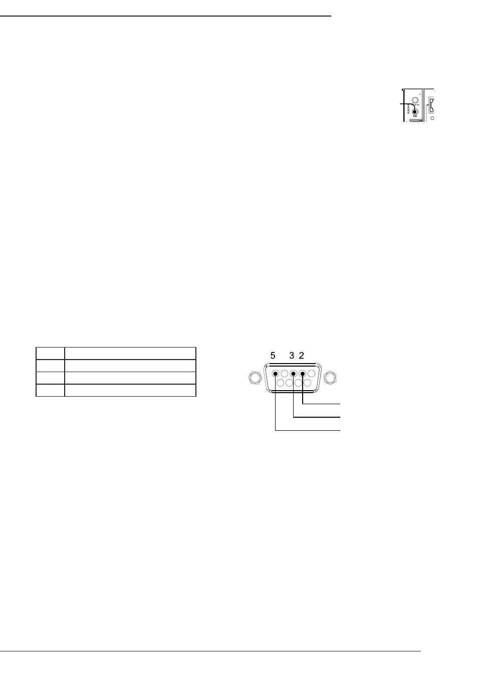
7.7.2. RS232 Control
To control the B-500-MTRX-230 with RS232, the devices must use the correct pin configuration for the control system
in use.
The matrix switcher receives control data on pin 2 (RxD – Data Receive) and transmits control data on pin 3
(TxD - Data Transmit). The connection cable between the matrix switcher and the Automation System will need
to be configured so that pin 2 (RxD) on the switcher is connected to the control system TxD pin, and pin 3 (TxD)
on the switcher is connected to the control system RxD (Receive Data) pin. See the diagram below for details.
Configuration for control system serial ports can vary. Refer to the documentation for the system in use to ensure
proper connection and configuration.
Note: This port is also used to communicate with a PC when using the PC Configuration Utility. Refer to the
Configuration Utility manual for details.
7.7.3. Ethernet/IP Control
The B-500-MTRX-230 includes an Ethernet port that can be used to control the device using Telnet Protocol. This port
follows TIA 568 A/B standards; please refer to these standards when terminating cables.
To configure the matrix switcher for use with the driver, it will be necessary to connect the unit to a PC and access it
with the Matrix Configuration Utility. See the Configuration Utility manual and the IP driver documentation for complete
setup instructions.
B-500-MTRX-230 RS232 Port Configuration
LINK
LINK
PWR
LINK
LINK
LINK
LINK
LINK
LINK
Engineered in the USA
Manufactured in Taiwan
IR IN ALL IR OUT
DB9 Female Connector
RxD (Data Receive)
TxD (Data Transmit)
GND
Pin
Function
2
RxD (Data Receive)
3
TxD (Data Transmit)
5
Ground/Common