2 hollow rotary, 22 4. installation – IAI America RCS2-RTC12L User Manual
Page 28
22
4. Installation
4.2 Hollow
Rotary
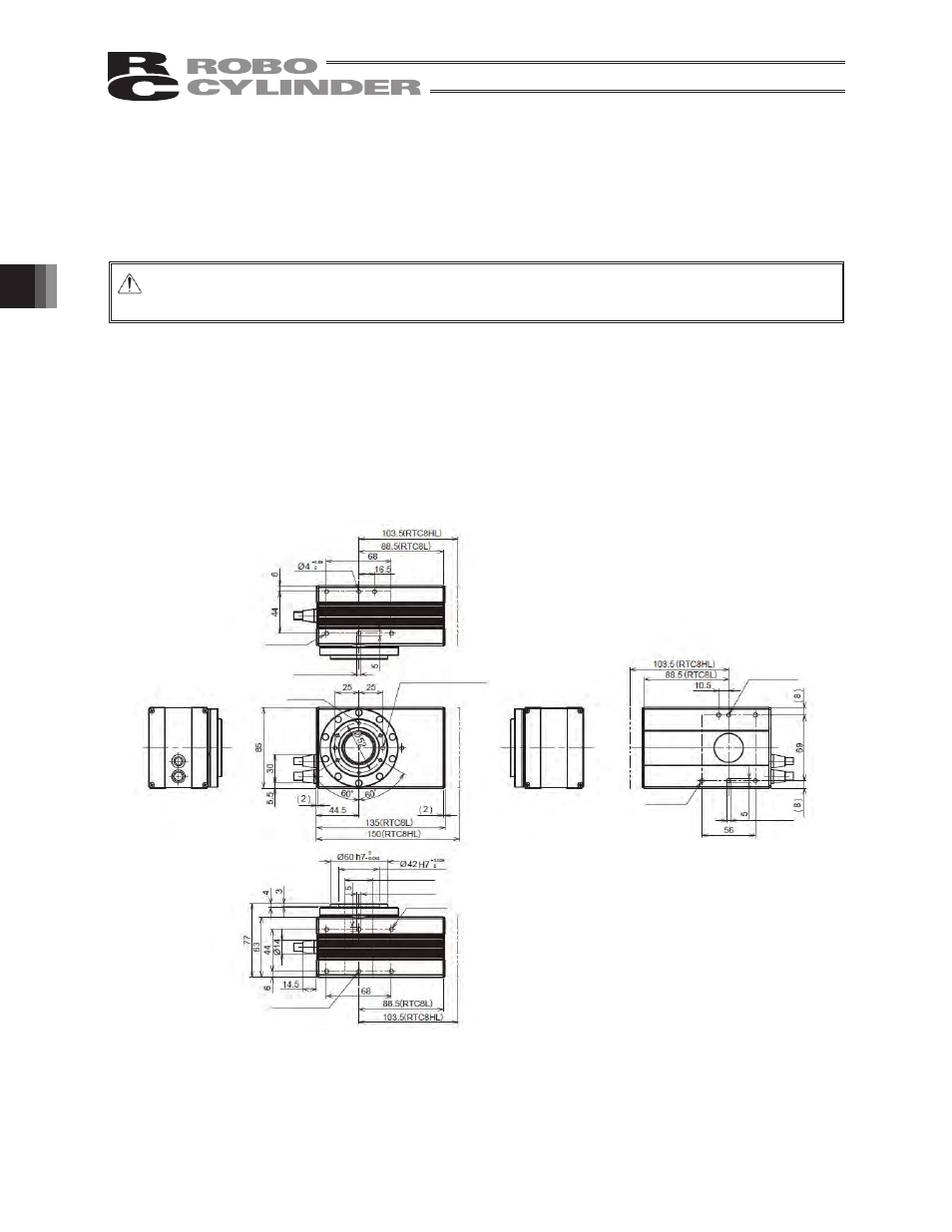
4.2.1 Installing the Actuator and a Tool on the Output Shaft
x The maximum screw-in depth varies depending on the mounting surface. Determine an appropriate
screw length by referring to the figure provided below.
Caution: Never use long screws exceeding the maximum screw-in depth. Use of such long screws
may cause damage to the internal mechanisms and electrical parts.
x Each mounting surface has circular holes and slotted holes for positioning pins. Use these holes as
necessary.
(Note) The actuator has been shipped with setscrews put on the actuator mounting screws to prevent
entry of foreign matters.
Remove the setscrews when installing the actuator.
[RTC8L, RTC8HL]
*
Depth 3.5
4-M5 Depth 10
*
6-M4 Depth 6
*
*
30 (Through)
4-M5 Depth 10
*
*
*
*
4-M5 Depth 10
(Maximum screw-in depth: 9)
(Note) The dimension denoted by “*” is different between the RTC8L and RTC8HL .
2 -
4 H7
Depth 5
+0.010
0
4 Depth
3.5
+0.05
0
4 Depth
3.5
+0.05
0
4 Depth
3.5
+0.05
0
4 Depth
4
+0.05
0
4 Depth
4
+0.05
0