2 installation of the main unit – IAI America RCP2W-SA16C User Manual
Page 30
2. Installation
24
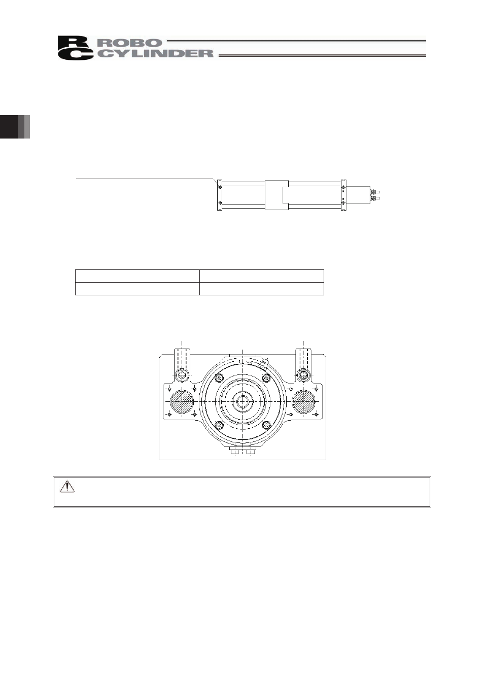
2.3.2 Installation of the Main Unit
• The base plates on both ends of the actuator have through holes. Use these holes when installing the
actuator.
• For the platform to install the actuator on, ensure the structure has enough stiffness to avoid vibration
being generated.
• The surface where the actuator will be mounted should be machined or be equally level and the
flatness tolerance between the actuator and the table should be within 0.05mm/m.
• Provide enough space around the actuator to permit maintenance work to be done.
䎃
䎃
䎃
䎃
䎃
䎃
䎃
䎃
Caution: The actuator has no reference plane on its base, so do not use it in applications
where traveling precision is required.
For installation, refer to the table below and use hexagon socket-head bolts of the specification
appropriate for the material of the frame on which the actuator is installed.
Steel frame
Aluminum frame
0
1
1
×
8
M
0
0
1
×
8
M
Use of high-tensile bolts conforming to ISO 10.9 or greater is recommended.
Recommended torque is 14 N⋅m (1.43 kgf⋅m).
4-9 drilled hole, φ14 counterbore depth 10