Securitron TM-2 User Manual
Page 6
PN# 500-16000
Page 6
Rev. C, 04/11
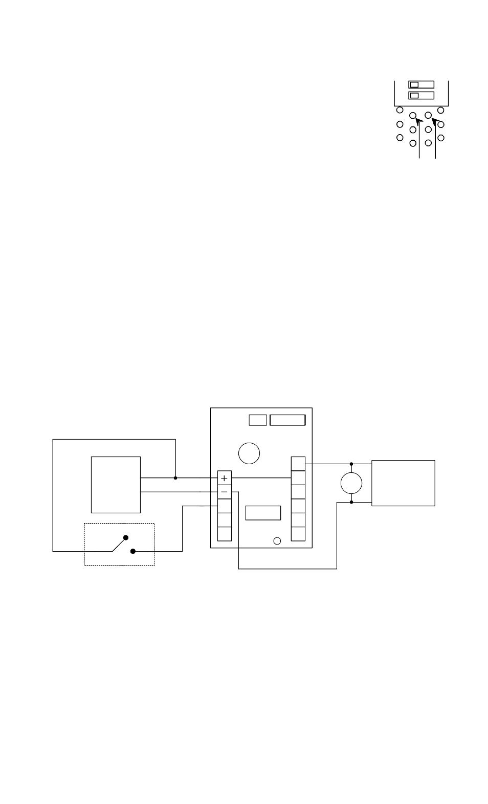
6.7 CYCLIC MODE
The cyclic mode is rarely used and is set up by a field soldering operation.
Install a wire jumper across the two pads shown to the right. With the jumper
installed, the state of Dip Switches 2, 3 and 4 do not matter. The cyclic mode
operates as follows: When the unit is powered, the relay energizes and
deenergizes back and forth with the time between state changes controlled by
the time setting Dip Switches. The cyclic mode is self triggering (when the unit
is powered). If the time is set to zero (all 8 time setting switches off) the relay
operates at 5 times per second allowing creation of a flashing light on a panel
for instance. Use as a flasher rapidly wears the relay so that after several
hundred hours of operation, the relay may fail. In flasher use, it is best to
employ the flash out function (terminal F) to operate an external LED. This is
described in section 5.
7. USE OF THE MOV (INDUCTIVE KICKBACK PROTECTION)
Note that a loose electronic component has been furnished with the TimeMaster. This is a metal
oxide varistor (MOV). Its purpose is to absorb inductive kickback if the TimeMaster's relay is
used to control an inductive load. When an inductive load is switched off by the relay, it emits a
high voltage spike in reverse polarity (kickback). This will considerably shorten the life of the
relay contacts and may also cause inconsistent operation of the TimeMaster owing to electronic
noise from the kickback interfering with the TimeMaster's microprocessor.
Inductive loads possess coils and generally include any electromagnetic device such as
solenoids, motors or electric locks. Installation of the MOV consists of attaching it in parallel
across the power input wires of the inductive load. The MOV is suitable for any inductive
load that operates from 12 to 24 volts AC or DC. If the TimeMaster is being used to
control a high voltage device with its own high voltage power supply, the MOV must
not be used as it will burn out. Note that if Securitron's Magnalock is being controlled by the
TimeMaster, the MOV is not necessary as the Magnalock has internal kickback protection. The
drawing below shows typical wiring which employs an inductive load, the MOV, a trigger switch
and the TimeMaster with its power supply.
FIG. 5: TYPICAL TIMEMASTER WIRING WITH USE OF MOV
NC
NO
C
T
R
F
C
NC
NO
RELAY
DIP SWITCHES
LED
12-24 V
AC OR DC
POWER
SUPPLY
INDUCTIVE
LOAD
MOV
IN THIS CIRCUIT, THE LOAD TURNS OFF WHEN THE TIMEMASTER RELAY ENERGIZES
TRIGGER SWITCH
8. MAGNACARE
LIFETIME REPLACEMENT WARRANTY
For warranty information visit
www.securitron.com/en/site/securitron/About/MagnaCare-Warranty/
5
4
BOTTOM OF DIP
SWITCH BLOCK
CONNECT THESE
TWO PADS BY
WIRE JUMPER