Securitron EXD User Manual
Page 8
PN# 500-13350
Page 8
Rev. E, 11/11
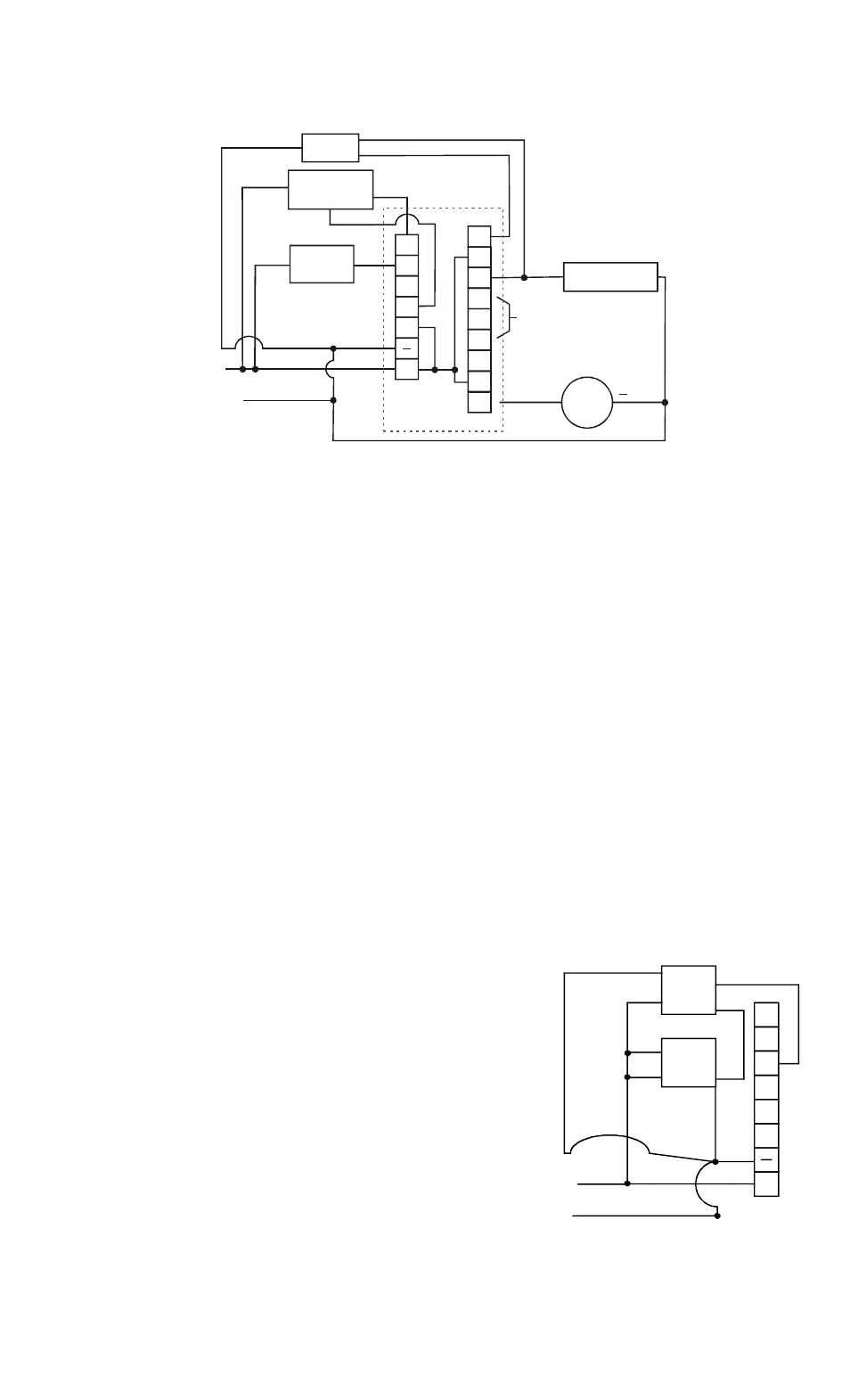
FIG 3: TYPICAL WIRING, EXD SYSTEM
WITH MECHANICAL BAR, MXD, SB-MXD OR LATCH MONITOR
LED
MK
KEYSWITCH
INITIATE
DEVICE
MAGNALOCK
NC
C3
NO
NC
C2
NO
NC
C1
NO
XDT BOARD
IF DOORSWITCH
REPLACES KEYSWITCH
IT MUST BE CLOSED
WHEN DOOR IS CLOSED
REMOTE ALARM
RELAY
RED
BL
A
C
K
SONA-
LERT
RED
GREEN
RED
+
V+
RS
IN
FE
BP
LS
+
BLACK
WHITE
BLUE
0V (NEG)
FR
O
M P
O
W
E
R
SU
PP
LY
NC
COM
6. INSTALLATION
6.1 PHYSICAL INSTALLATION
The Magnalock and initiate device should be physically mounted on the door according to their
individual instructions. If the MK keyswitch is used in this installation, its instructions explain
mounting the user supplied mortise cylinder. The XDT timer is supplied in its own enclosure
(Model BA-XDT or model FA-XDT), and will either surface mount above the door or flush mount
next to the door.
6.2 WIRING
6.2.1 BASIC WIRING
Please refer to Figure 2 which shows typical wiring for an EXD with a Touch Sense Bar or
Touch Sense Handle or Figure 3 for an EXD system with switch equipped mechanical panic
bar, MXD, SB-MXD or Latch Monitor. These drawings show interconnections of all system
components except the power supply-fire alarm connections. Wired as shown, the systems fully
meet the exit delay code requirements.
Note that with respect to Figure 3, the two wires coming from the un-powered initiate device are
labeled “COM” and “NC”. The circuit between these two wires opens when the initiate device
is used. In the case of the MXD and SB-MXD, both devices have only two wires so confusion
is impossible.
The bicolor LED in the reset keyswitch is connected so that it is green in the "normal" locked
condition. It illuminates red when the lock has been released following the exit delay or bypass.
Therefore the LED "invites" the user to turn the key and reset the door.
6.2.2 DOUBLE DOOR WIRING
A double door can be accommodated by using 2
Magnalocks and 2 initiate devices. Only a single timer
and reset keyswitch are necessary. With this type of
wiring, activating the device on either door releases the
Magnalocks on both doors. The Magnalocks are
connected in parallel (red to red; black to black). The
initiate device switch contacts are connected in series.
With the Touch Sense Bar or Touch Sense Handle, the
connection is somewhat complicated as sensor power is
connected in parallel but sensor contacts are connected
in series. The small drawing to the right shows the
detail of the connections. To complete the installation,
follow Figure 2 for connection of the other components
and, as explained above, connect the 2 Magnalocks in
parallel. When one of the un-powered initiate devices
+
LS
BP
FE
IN
RS
0V (NEG)
+V
RED
WHT
GR
E
E
N
BL
AC
K
TSB-3/
TSH #2
TSB-3/
TSH #1
WHT
GREEN
RED
BLACK
DC