Securitron EXD User Manual
Page 5
PN# 500-13350
Page 5
Rev. E, 11/11
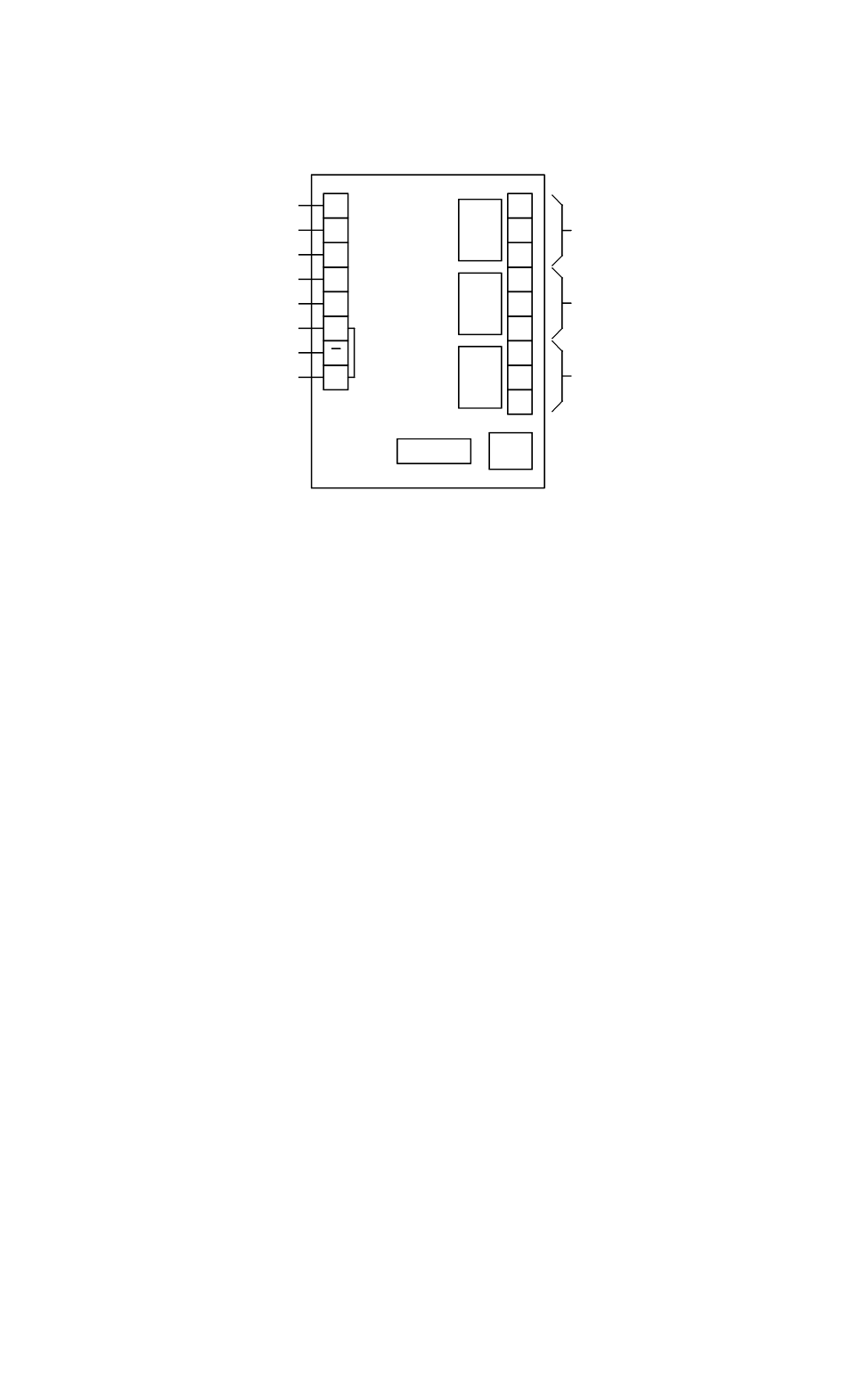
The XDT logic timer is the heart of any EXD system. The following drawing is an overview of the
timer's functions and is useful for reference as later parts of this manual discuss wiring and
enabling optional functions.
FIG. 1: XDT LOGIC TIMER OVERVIEW
NO
NC
C1
C2
C3
+
LS
BP
FE
IN
RS
NC
NC
NO
NO
DIPS
LOCK CONTROL
RELAY
LOCAL ALARM
REMOTE ALARM
RELAY
RELAY
RESET INPUT
INITIATE INPUT
LOCK STATUS INPUT
BYPASS INPUT
FREE EGRESS INPUT
0V (NEG) POWER
+V POWER
NOTE: INPUTS OPERATE
BY BEING CONNECTED TO +V
NORMALLY ENERGIZED
NORMALLY DEENERGIZED
NORMALLY ENERGIZED
DC
DELAY CONTROL TERMINAL
4. SPECIFIC CODE REQUIREMENTS
We must strongly emphasize that the following sections on code requirements should not be
considered definitive. They represent Securitron's best understanding of the individual codes
at the time of this manual's most recent revision. Codes, however, can change suddenly and are
also subject to local interpretations that may differ from the descriptions that follow.
You should consider these descriptions as a starting point which should be confirmed
or altered by the local authority having jurisdiction.
Also, many customers are interested in the issue of UL testing for systems of this type. EXD
systems are UL listed under the UL FWAX category which is also called Special Locking
Arrangements. UL tests all systems applying for such a listing under a test standard which
presently only recognizes the method of operation detailed in the NFPA 101 code for Special
Locking Arrangements. This is a limitation of the UL test standards. In many parts of the United
States, however, operational requirements as set by the authority having jurisdiction will vary in
minor ways from the exact requirements of NFPA 101. The EXD system has been designed to be
able to perform these alterations in operating sequence so that it can meet differing operating
requirements as set by the different model codes. UL, however, has tested only operation
under NFPA 101 and therefore takes no position on the ability of the EXD system to meet
alternate code requirements. The EXD's ability to do this is warranteed by Securitron.
In the following 5 sections, we describe individual code requirements in 4 areas: Nuisance delay,
Release delay, Relocking and Power. The main issue in the Power function is whether battery
backup can be applied to the locking system to keep the door functional in a power failure.
4.1 NFPA 101 (SPECIAL LOCKING ARRANGEMENTS)
This code by the National Fire Protective Association was the first implementation of delayed exit. It formed
the basis for the different model code versions which follow and is still used in many specifications.
NUISANCE DELAY: Permitted up to 3 seconds.
RELEASE DELAY: 15 seconds or extension to 30 seconds with local approval.
RELOCKING: Must be "manual". This is generally interpreted to mean that a doorswitch can not
be used for relocking. A keyswitch is the typical technique used.
POWER: The door must release when DC power to it is cut off. This means that battery backup
of the system power supply may be acceptable, but this is a point to confirm with the local
authority.