Securitron TSB_Series User Manual
Page 5
PN#
500-16410
Page
5
Rev.
E,
02/12
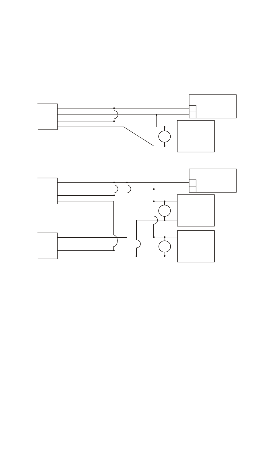
following drawing (Figure 4) shows typical connections of sensor, power supply and fail safe (released
when powered) lock. Fail secure electric locks are normally not permitted for use with the TSB on
required exit applications. NO contacts, however, are available from the sensor for special signaling
applications and for integration with the Request to Exit (REX) function of an access control installation, as
will be explained. Note installation of the MOV in parallel with the electric lock. The MOV is supplied loose
with the TSB. It is a black or blue disk-like component with two bare wires for connection. The MOV acts
to suppress the lock’s inductive kickback which will greatly shorten the life of the relay contacts if not
suppressed. To work properly it should be spliced in as close to the electric lock as possible. It has no
polarity. If, however, Securitron's Magnalock is used in the installation, the MOV is not
necessary as the Magnalock is internally suppressed.
FIG. 4: TSB WIRING FOR MAGNETIC LOCK
+
_
POWER SUPPLY
12-24 VOLTS
CABLE
RED (+ POWER)
BLACK (- POWER)
WHITE (RELAY COM1)
GREEN (RELAY N.C.1)
MOV
MAGNETIC
LOCK
+
_
CABLE
RED (+ POWER)
BLACK (- POWER)
WHITE (RELAY COM1)
GREEN (RELAY N.C.1)
MOV
MAGNETIC
LOCK
+
_
+
_
POWER SUPPLY
12-24 VOLTS
CABLE
RED (+ POWER)
BLACK (- POWER)
WHITE (RELAY COM1)
GREEN (RELAY N.C.1)
MOV
MAGNETIC
LOCK
+
_
TSB WIRING FOR ONE MAGNETIC LOCK
TSB WIRING FOR MULTIPLE MAGNETIC LOCKS
NOTE 1: MOV NOT NEEDED IF SECURITRON MAGNALOCK USED
NOTE 2: POWER SUPPLY MUST ALWAYS CONNECT DIRECTLY TO SENSOR
NOTE 3: IN POWER HOOK UP, POLARITY MUST BE OBSERVED
When connecting power, polarity must be observed. As an additional safety feature, the TSB
includes a low voltage sensing circuit. The unit will keep working normally if input voltage declines
until it reaches roughly 9 volts. At that point, the TSB will automatically act as if all power was removed.
If a lock is being controlled, it will release. Input voltage could decline if the unit was being operated on
batteries and the batteries were discharging or because of a fault in the power supply.
3.3 DOUBLE BREAK WIRING
Many installations include a controlled access device such as a digital keypad or card reader. Such devices
typically have a REX (request to exit) input. When dry contacts close on this input, the entry device will
open the lock for the same amount of time that is programmed for entry. Use of the REX input for exit
has two benefits: you pick up timed exiting and also in the case of most entry controls, the REX input
must be used for exiting to avoid an alarm condition at the door.
If the REX input alone is used for exiting a safety/reliability problem will exist. If the entry
device malfunctions, exit will not be possible and people may be trapped. We therefore always
recommend double break wiring which is supported by the TSB because of its two pole relay. The TSB's
NC contacts are used to break power to the fail safe electric lock while its NO contacts trip the REX input