Securitron TSB_Series User Manual
Page 3
PN#
500-16410
Page
3
Rev.
E,
02/12
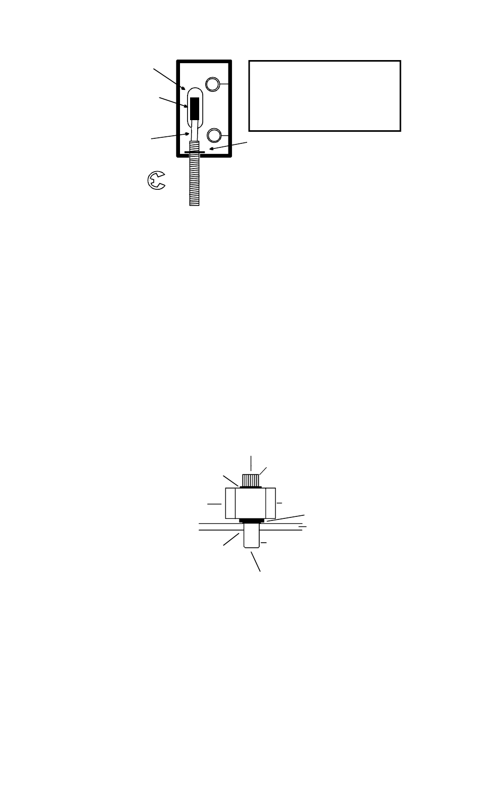
FIG. 1: REAR VIEW OF END PIECE SHOWING CABLE ROUTING THROUGH END PIECE
"E" CLAMP
STAINLESS DOOR CORD INSERTS
INTO HOLE DRILLED IN BOTTOM
OF END PIECE. SECURES WITH
"E" CLAMP
"E" CLAMP INSTALLED TO
SECURE STAINLESS CORD
6 CONDUCTOR
JACKETED CABLE
CABLE CONNECTOR
WHICH ATTACHES
TO CIRCUIT BOARD
ELONGATED SLOT
RECOMMENDED TOOLS
MEDIUM, SMALL PHILLIPS DRIVERS
DRILL MOTOR
1/4", 3/8, 1/8" DRILL BITS
WIRE CUTTER/STRIPPER
VOLT/OHM METER
CRIMP CONNECTORS AND PLIERS
If you are using the preferred method of pulling the cable through the door, the cable must be inserted
into the 3/8" wireway hole you have drilled in the door. The connector will be left protruding from this
hole. The connector will pass through the elongated slot in the end piece, so the cable should be pulled
first and then the bar may be mounted. If you are using the door cord rather than a transfer hinge or
pivot to bring the cable from the door into the frame, remember that you must pass the cable through the
cord before fishing it into the frame.
Note that if, for any special reason, you find it desirable to pull the cable through the bar, this must not
be done. The cable must always exit the bar at the end piece which includes the circuit board.
If it goes through the bar, it creates electronic interference with the touch sensing function which voids
the performance of the bar.
2.5 BAR MOUNTING
The holes you have drilled for bar mounting (Section 2.2) were different depending on the type of door.
Similarly the final mounting procedure depends on the door type.
In the case of a hollow metal door, identify the four supplied blind nuts. The nuts are used as follows.
Insert the nuts with the knurl engaging the edge of each hole. Then utilize the supplied collapsing tool to
collapse the nuts. Use of the tool is shown in Figure 2. Next, use the shorter (2 1/4" or 54 mm)) supplied
machine screws. Place a tooth washer under the head of each screw and mount the bar. Do not over
torque.
FIG. 2: COLLAPSING THE BLIND NUTS (METAL DOOR)
DOOR
TOOL
CAP SCREW
BLIND NUT
DRILL 3/8" (9.5MM) HOLE
NUT AS SHOWN
PRESS IN BLIND
COLLAPSES WHEN CAP SCREW
TURNED WITH ALLEN WRENCH
WHILE TOOL HELD FAST
WITH BOX WRENCH
WHILE TURNING WITH ALLEN
WRENCH, PRESS IN TO KEEP
NUT SEATED IN DOOR
HOLD WITH WRENCH OR
CAP SCREW
VISE GRIP WHILE TURNING
FLAT WASHER
KNURL
For through bolt + sex bolt mounting, you will be using longer 3 1/2" (90 mm) machine screws with
the sex bolts supplied in the TSB-TDM kit. You should have already drilled 1/4" (6 mm) holes through the
door. The next step is to install the sex bolts. From the outside of the door, enlarge the holes to 3/8"
(9.5 mm) diameter, 1" (25 mm) deep. Push in the sex bolts. Then place a tooth washer under the head
of each screw and mount the bar. Note that the screw length is suitable for a 1 3/4" (44 mm) thick door.
Nearly all North American commercial doors are this thickness. If you have a door of different thickness,
a number of techniques can be applied. Screws of different lengths can be purchased or the supplied
screws may be cut (if the door is thinner). Since the sex bolts are short, however, some final adjustments
may be necessary. Spacing washers may be added under the screw heads but if you raise the heads too
high they will interfere with removal of the circuit board (if this ever becomes necessary). The board can
still be removed but the mounting screws will have to come out first and this is inconvenient. Another