Securitron DK-12 User Manual
Page 2
PN# 500-24010
Page 2
Rev. C, 04/11
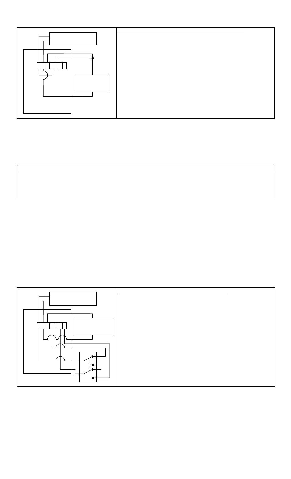
Basic Power and Electric Lock Connections:
Connect supply to ‘AC/DC+’ and ‘AC/DC-’ terminals.
Connect ‘AC/DC+’ terminal to ‘COM’ terminal.
For fail-safe operation connect ‘NC’ terminal to one
lead of lock (positive lead if a DC lock).
For fail-secure operation connect ‘NO’ terminal to one
lead of lock (positive lead if a DC lock).
Connect other lead of lock to the ‘AC/DC-’ terminal.
NOTE: Use a DC supply for a DC lock and an AC
supply for an AC lock. Ensure the supply has the
capacity to operate both the lock and the DK-12.
Relay contact MOV protection is built into the DK-
12.
4. REX SOURCE AND INPUT
The REX (Request To Exit) function allows the door to be opened from the inside when an
electric lock (such as a magnetic lock) is securing the door. To use the REX a normally open
switch is placed between the ‘SRC’ and “REX’ terminals. When this switch is pushed/closed it
operates the DK-12 relay the same as if a code were entered.
REX CHARACTERISTICS
Holding the REX switch closed will keep the lock released.
When the REX switch re-opens the lock will remain released for the programmed time.
When in toggle mode the REX switch will toggle the relay state.
When in lockout mode the REX switch will still release the lock.
When using exit switches the possibility must be considered that an electronic failure may occur
to the DK-12 and people will not be able to exit. If the DK-12 controls the only door exiting
the area additional steps should be taken to improve the reliability of the exiting so as
to avoid trapping people. This can most easily be done by implementing a secondary means
of releasing the lock not dependant on the DK-12’s REX input. Additional switch contacts should
be used which directly control the electric lock. In the case of a fail-safe lock, which should
always be employed when there is only one exit path, this can be easily accomplished with
“double break” wiring between the exit button, electric lock, and DK-12. The exit button must
have normally open and normally closed contacts and be of the DPDT type. Exit buttons that fit
this need are available from Securitron. Note that you should always consult your local
building department when securing doors that are part of an emergency exit path to
make sure you are complying with local codes.
Double Break Wiring For Free Egress:
Connect supply to ‘AC/DC+’ and ‘AC/DC-’ terminals.
Connect ‘AC/DC+’ terminal to one common terminal of
the DPDT switch.
Connect the normally closed contact of that common to
the ‘COM’ terminal.
Connect ‘NC’ terminal to one lead of lock (positive lead
if a DC lock).
Connect other lead of lock to the ‘AC/DC-’ terminal.
Connect ‘SRC’ to the other common terminal of the
DPDT switch.
Connect the normally open contact of that common to
the ‘REX” terminal.
Because the DK-12 was designed for use with AC and DC voltages the ‘SRC’ output was provided
to supply a current limited DC source for the REX switch. The above diagram can be redrawn for
use with a SPDT switch if required, however, an external resistor must be provided and
this setup can only be done with a DC power supply; if an AC power supply is used the
REX must be connected to the ‘SRC’ output.
1 2 3 4 5 6 7
DK-12
Back Side
Power Supply
Fail-Safe
Electric Lock
NO
NO
NC
NC
C
C
DPDT Switch
1 2 3 4 5 6 7
DK-12
Back Side
Power Supply
Electric
Lock
If Fail Safe
If Fail
Secure