Securitron MCL-24 User Manual
Page 5
PN# 500-19100
Page 5
Rev. C, 04/11
4. Install Magnalock Body using four (4) #6 x 1” Long Pan Head Wood Screws (Item
#10). Tighten the screws firmly using a Phillips Head Screwdriver.
5. Run Power Cable to terminal connection as required.
6. OPERATIONAL INSTRUCTIONS
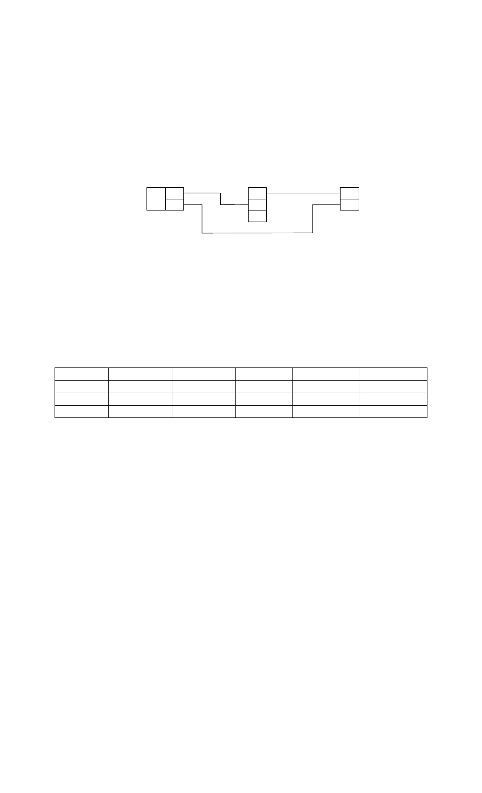
The Securitron Model MCL-24 is a Fail Safe locking device (power to lock). To power the MCL-24
you simply apply positive voltage DC to the red wire of the Magnalock through a normally closed
control switch. The black wire of the Magnalock should return directly to the negative DC.
Example
-
+
120
VAC
IN
VDC
OUT
POWER SUPPLY
NC
C
NO
SPDT
CONTROL
SWITCH
-
+
MCL-24
RED
BLK
6.1. WIRE GAUGE SIZING
If the power supply is distant from the lock, voltage will be lost (dropped) in the connecting
wires so that the Magnalock will not receive full voltage. The following chart shows the
minimum wire gauge that will hold voltage drop to an acceptable 5% for different lock to
power supply distances. Proper use of the chart assumes a dedicated pair of wires to power
each Magnalock (no common negative). Note that a Magnalock operating on 24 volts is a
much better choice for long wire runs as it has 4 times the resistance of a 12 volt installation.
Also note that the correct calculation of wire sizing is a very important issue as the installer is
responsible to insure that adequate voltage is supplied to any load. In multiple device
installations, the calculation can become quite complex so refer to Section 9 Appendix A for a
more complete discussion.
Distance Gauge
12V Gauge
24V Distance
Gauge 12V
Gauge 24V
80 FT
20 GA
24 GA
800 FT
10 GA
16 GA
200 FT
17 GA
22 GA
1500 FT
8 GA
14 GA
400 FT
14 GA
20 GA
3000 FT
N/A
12 GA
7. MAINTENANCE
Maintenance for MCL-24 is very simple. Once every six months we recommend taking a clean
cloth and rubbing alcohol or a non-abrasive cleaner and wiping down the face of the Magnalock
and the Armature. This prevents a build up of foreign materials from the air making the
Magnalock stick.
8. TROUBLESHOOTING
PROBLEM: No magnetic attraction between magnet and strike plate.
First be sure the Magnalock is being correctly powered with DC voltage. This includes
connecting the power wires with correct polarity. Positive must go to red and negative to
black. If the magnet body is wired in reverse polarity, it will not be damaged, but it will not
operate. If the unit continues to appear dead, it must be electrically checked with an
Ammeter. It must be powered with the correct input voltage and checked to see if it draws
the specified current. If the unit meters correctly, it is putting out the correct magnetic field
and the problem must lie in the mounting of the strike.
PROBLEM: The lock does not release.
When power is removed from it, the Magnalock must release. Therefore the complaint of
"lock will not release" is either mechanical bonding via vandalism or a failure to completely
release power. By mechanical bonding, we simply mean that glue has been applied between
the armature and magnet as a prank. Failure to completely release power is generally a
wiring integrity problem. What happens is that an upstream switch removes power from the
wires going to the Magnalock, but through an installation error, the wires have their
insulation abraded between the switch and lock so that partial or full power can leak in from
another Magnalock or other DC device with similarly abraded wiring. This is most likely to