Document configuration settings – Securitron M680 User Manual
Page 5
PN# 500-10550
Page 5
Rev. C, 08/12
J1
Terminal Block 1
Tamper Switch
A 2-wire terminal block providing a SPDT contact that
changes state as determined by JP1 when the cover is
sensed to be removed by SW1.
J5
Terminal Block 5
Input Power
A 2-wire terminal block providing connection to the power
supply. Position 1 is (+). Position 2 is (-).
J6
(available on M680
models only)
Terminal Block 6
BondSTAT
A 3-wire terminal block providing a SPDT 1-Form C
contact that changes state when the BondSTAT bond is
interrupted.
J8
(available on M680
models only)
Terminal Block 8
Door Position Switch
A 2 wire terminal block providing 1 SPST contact that
state change is determined by Jumper 3 based on the
magnet’s contact with the strike plate. (Available on
M680 only)
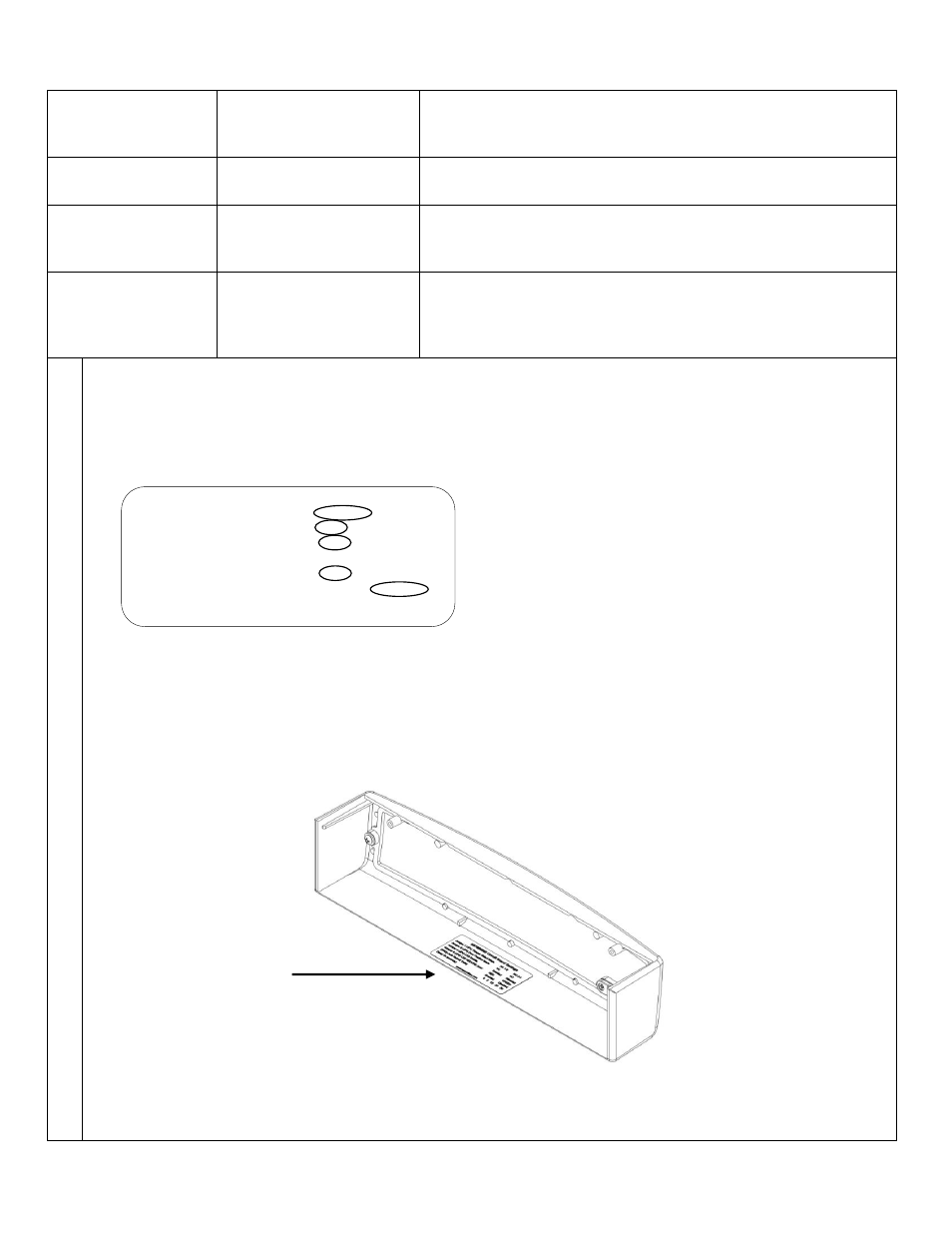
3.
Document Configuration Settings
The Board Settings are now complete. Copy your settings onto the adhesive-backed Circuit Board Settings label
enclosed with the mounting hardware packet.
Important! Complete the label and affix to the inside cover of your Magnalock
This information will be needed if the lock needs to be serviced, replaced or inspected.
Note: The example shows the
Default settings. Your settings may
vary, based on your checklist.
NO = Normally Open
NC = Normally Closed
M670/M680 Settings
Jumper 4 (JP4) LED Enable
ENABLED DISABLED
Jumper 5 (JP5) LED SECURE Color
RED
GREEN
*Jumper 1 (JP1)Tamper Select Mode NC 1-2
NO 2-3
*Jumper 2 (JP2) Request to Exit Mode NO 1-2
NC 2-3
*Jumper 3 (JP3) Door Position Mode NC 1-2
NO 2-3
*(SW2) Auto Relock Delay
ENABLED DISABLED
*Delay (in seconds)
0 5 10 20 30
*available on select models
1-800-MAGLOCK