Securitron M680 User Manual
Page 4
PN# 500-10550
Page 4
Rev. C, 08/12
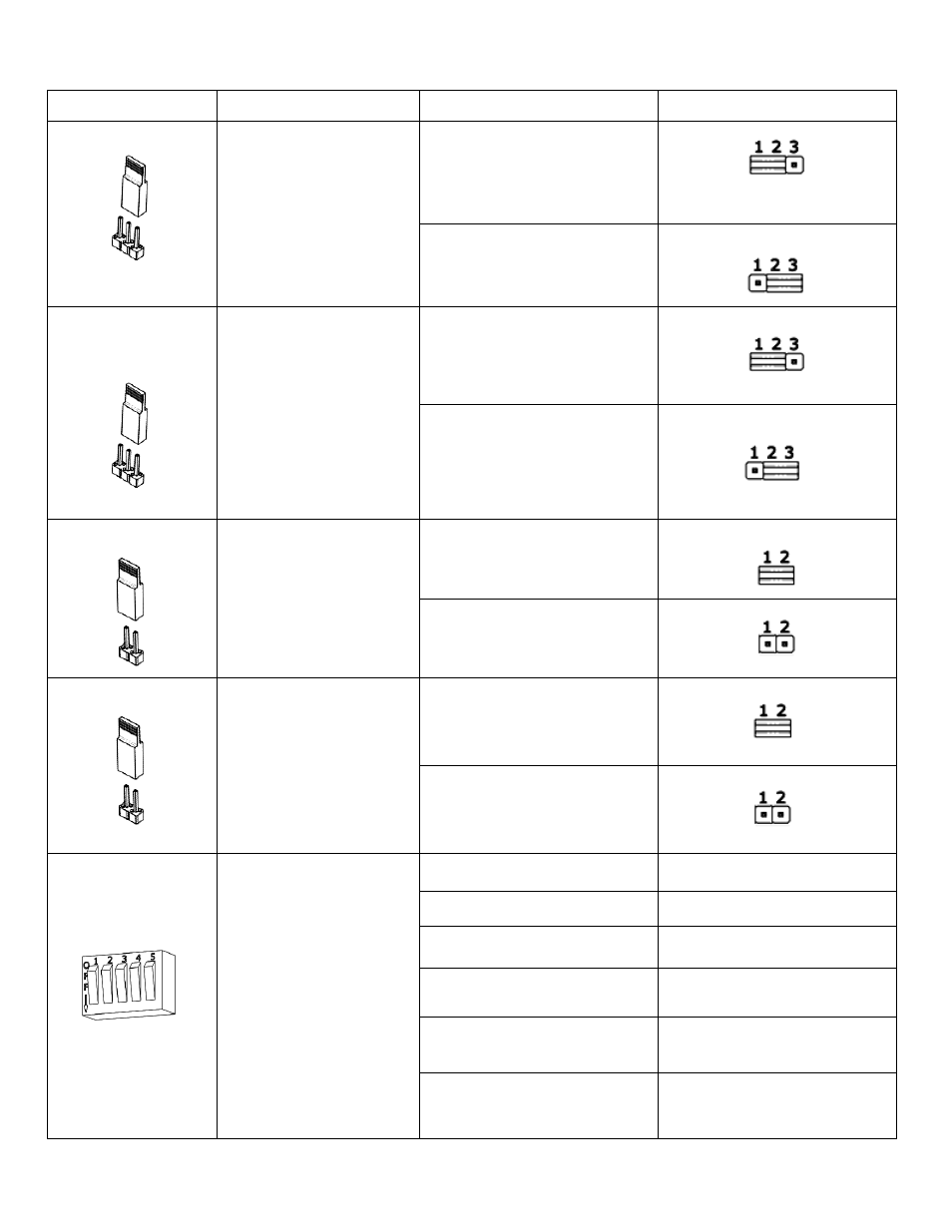
Component Label
Component Name
Selection
Position
JP1
Jumper 1: Tamper
Switch Mode Select
A 3-pin jumper that
controls the output
setting for Tamper
Switch SW1 at
Terminal Block J1.
(NC) Normally Closed
Circuit Closed when Cover
Closed (default setting)
(NO) Normally Open
Circuit Open when Cover
Closed
JP3
(available on M680
models only)
Jumper 3:
Door Position
Mode Select
A 3-pin jumper that
controls the output
setting for the Door
Position Switch (DPS)
in Terminal Block J8
Position 1 & 2.
(NC) Normally Closed
Circuit Closed when Door is
Closed (default setting)
(NO) Normally Open
Circuit Open when Door is
Closed
JP4
Jumper 4:
LED Enable
A 2-pin jumper that
enables the LED.
LED ENABLED
(default setting)
LED DISABLED
(jumper removed)
JP5
Jumper 5:
LED Color Select
A 2-pin jumper that
controls the color of the
LED output. Output
options are red or
green.
SECURE = RED LED
(default setting)
SECURE = GREEN LED
(jumper removed)
SW2
(available on M680
models only)
DIP Switch
Auto Relock Timer
Enable and Delay
Selection
The Auto Relock Delay
Timer is disabled by
default. The delay can
be enabled by setting
Switch 4 to ON, and
then selecting a time
delay with Switch 1 and
Switch 2.
DISABLE Delay Timer
Switch 4 OFF (default)
ENABLE Delay Timer
Switch 4 ON
5 second delay
Switch1 OFF, Switch2 OFF
10 second delay
Switch1 OFF, Switch2 ON
20 second delay
Switch1 ON, Switch2 OFF
30 second delay
Switch1 ON, Switch2 ON