Securitron M68 (L, S and LS with D and T Options) User Manual
Page 11
PN#
500-21400
Page
11
Rev. B, 8/07
8. APPENDICES
A.
WIRE GAUGE SIZING
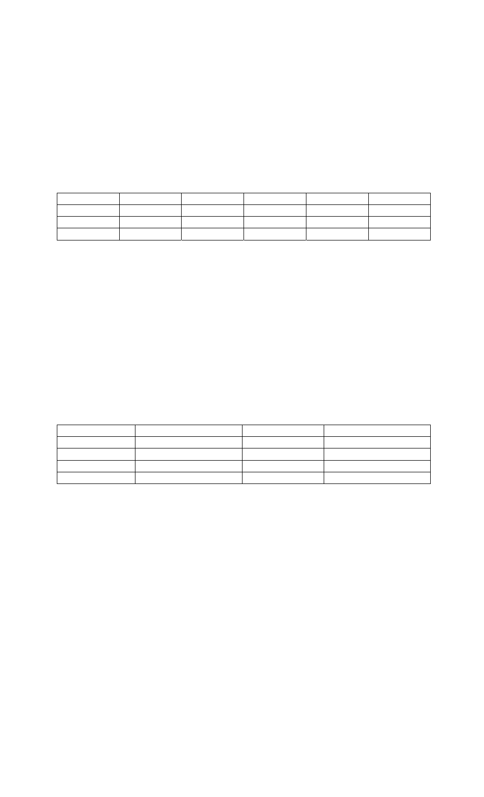
If the power supply is distant from the lock, voltage will be lost (dropped) in the connecting
wires so that the Magnalock will not receive full voltage. The following chart shows the
minimum wire gauge that will hold voltage drop to an acceptable 5% for different lock to
power supply distances. Proper use of the chart assumes a dedicated pair of wires to power
each Magnalock (no common negative). Note that a Magnalock operating on 24 volts is a
much better choice for long wire runs as it has 4 times the resistance of a 12 volt installation.
Also note that the correct calculation of wire sizing is a very important issue as the installer is
responsible to insure that adequate voltage is supplied to any load. In multiple device
installations, the calculation can become quite complex so refer to the following section
“Calculating Wire Gauge Sizing” for a more complete discussion.
Distance
Gauge 12V Gauge 24V
Distance Gauge
12V
Gauge
24V
100 FT
24 GA
24 GA
800 FT
18 GA
22 GA
200 FT
22 GA
24 GA
1500 FT
14 GA
18 GA
400 FT
20 GA
22 GA
2000 FT
14 GA
18 GA
CALCULATING WIRE GAUGE SIZING
The general practice of wire sizing in a DC circuit is to avoid causing voltage drops in
connecting wires that reduce the voltage available to operate the device. As Magnalocks are
very low power devices, they can be operated long distances from their power source. For any
job that includes long wire runs, the installer must be able to calculate the correct gauge of
wire to avoid excessive voltage drops.
This is done by taking the current draw of the lock and multiplying by the resistance of the
wire I x R = Voltage drop (i.e. 0.100A x 10.1 Ohms = 1.01 Volts dropped across the wire). For
all intents and purposes it can be said that a 5% drop in voltage is acceptable so if this were a
24 Volt system (24 Volts x .05 = 1.2 Volts) a 1.01 Volt drop would be within tolerance.
To calculate the wire resistance, you need to know the distance from the power supply to the
Magnalock and the gauge (thickness) of the wire. The following chart shows wire resistance
per 1000 ft (305 meters):
Wire Gauge
Resistance/1,000 ft
Wire Gauge
Resistance/1,000 ft
8 Gauge
.6 Ohms
16 Gauge
4.1 Ohms
10 Gauge
1.0 Ohms
18 Gauge
6.4 Ohms
12 Gauge
1.6 Ohms
20 Gauge
10.1 Ohms
14 Gauge
2.5 Ohms
22 Gauge
16.0 Ohms
B.
CONSIDERATIONS FOR MAXIMUM PHYSICAL SECURITY
M38 and M68 Magnalocks carry rated holding forces of 600 lbs. [272 Kg] and 1,200 lbs. [544
Kg] respectively. There are several installation and application variables to be considered
which affect the security level that may be obtained while using a Magnalock.
In the case of wooden doors (other than solid hardwoods), aluminum frame glass doors, and
hollow metal doors, the M38 should be employed in a “traffic control” mode. This is because a
determined assault on these types of door/lock configurations has the potential of “popping”
this model open. The M68 is generally stronger that the door itself. Users have logged
periodic cases of an assault where the door has been destroyed leaving the Magnalock intact
and still retaining the piece of the door where the strike was mounted.
A pry bar may be used to try to pry the door open. However, what generally occurs is that the
door will experience material failure. The pry bar tears (in the case of wood) or bends (metal)
the door material without defeating the lock. The general fact that a Magnalock mounts on the
other side of the door from the attacker is an important contributor to its strong resistance to
assault.
The concept of preferring a door that gives also affects the issue of physical security on
different door types. Oddly enough, the characteristics that make an inswinging door strong