Securitron M34R_Series User Manual
Page 4
PN# 500-13800
Page 4
Rev. D, 04/11
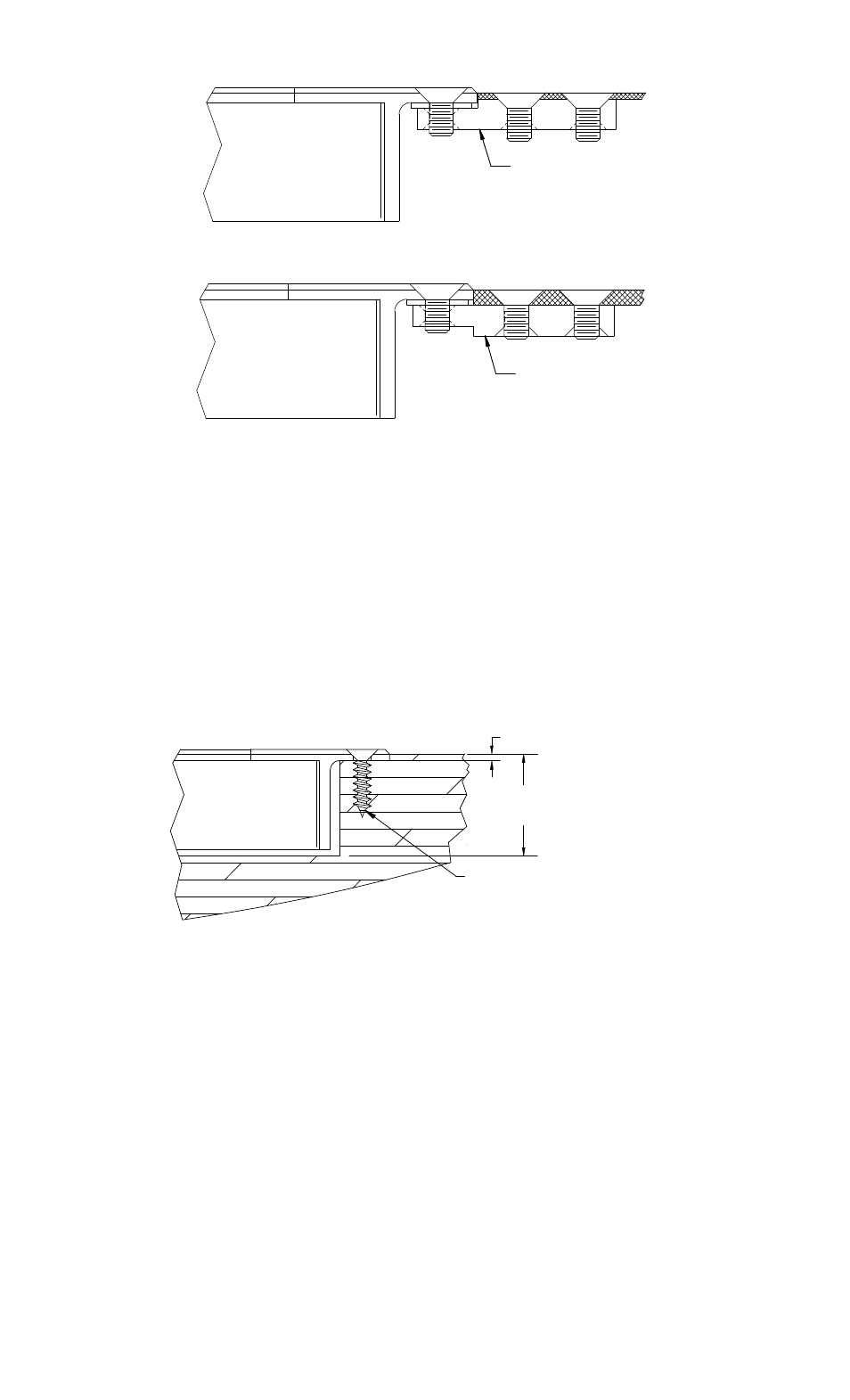
Flush Mount Bracket
(Note Orientation)
Figure 3 - Flush mount bracket mounting (thin wall frame)
Flush Mount Bracket
(Note Orientation)
Figure 4 - Flush mount bracket mounting (thick wall frame)
APPLY THE PROVIDED THREAD LOCKING COMPOUND TO ALL MOUNTING SCREW
THREADS.
5.4.2 Solid Wood Door Frames
Prepare the door frame in accordance with Section 5.3.1.
Place the lock body into the cutout area to ensure proper fit. As necessary, perform any filing or
chiseling necessary to ensure the mortised fit. Ensure all necessary holes required to mount the
magnet body into place as indicated on the template have been provided. The depth of the
mortise cut out is important depending on the lock model being installed. The minimum depth
of the cut out is noted in Figure 5 below and includes enough distance for the required recess
depth of 1/16” [1.5mm] for the mounting brackets. Install the lock using the wood mounting
screws as shown in Figure 5.
Mortise Depth
1-1/8"
1/16"
Flathead Sheet Metal Screw
#10 x 3/4"
Figure 5 - Wood frame lock bracket mounting
5.5 Mounting the Strike Assembly
5.5.1 Hollow Metal Door
Prepare the door in accordance with Section 5.3.2.
Using the provided template and Figure 2 for reference, install the strike mounting block into
the edge of the door using a hex wrench and the provided mounting screws and sex bolts.
Assemble the strike to the mounting block using the strike mounting screw, plastic strike
bushing and one, two or three of the rubber washers to complete the installation.
APPLY THE PROVIDED THREAD LOCKING COMPOUND TO ALL MOUNTING SCREW AND
SEX BOLT THREADS.