Ransburg, Basic operation, Kv test jumper – Ransburg Vector R Series Cascade 79523 R90 Waterborne User Manual
Page 33
Vector R Series Cascade Applicators - Operation
Ransburg
29
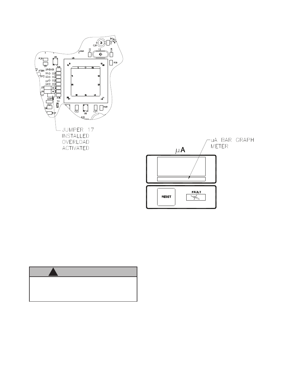
Figure 11: Jumper Location -
Overload Activation
BASIC OPERATION
Triggering
High voltage is actuated by pulling the trigger
to start the flow of atomizing and fan control air
through the applicator. When the applicator is
triggered, an air flow switch is activated, the kV
setpoint is displayed on the kV display, the actual
current draw on the µA display and the high volt-
age light illuminates. Under the µA display is a
bar graph meter that illuminates according to the
actual current draw.
Figure 12: µA Bar Graph Display
The green and yellow regions of the bar graph
meter indicate output current is in the optimum
range for maximum transfer efficiency. The red
region of the bar graph indicates high output current
causing decreased transfer efficiency.
The display at the rear of the applicator also
doubles as a microamp bar graph meter when
high voltage is on (see Figure 13). Its function is
similar to that of the control unit bar graph display.
KV TEST JUMPER
To assist in testing and troubleshooting, a jumper
(J8) has been added to the main PC board. By
covering (shorting) both terminals of this jumper,
the high voltage to the spray applicator can be
activated. Thus, for testing and troubleshooting,
high voltage output can be obtained without the
need to trigger air through the spray applicator.
After testing, the jumper must be repositioned so
that it covers only one terminal (open) or the high
voltage will stay on all the time. (See Figure 8 for
location of test jumper J8.)
If jumper J8 is left covering (shorting)
both terminals, high voltage will be on when-
ever AC power is turned on.
C A U T I O N
!
AH-06-01.13