Ransburg, Lockouts – Ransburg Vector R Series Cascade 79523 R90 Waterborne User Manual
Page 31
Vector R Series Cascade Applicators - Operation
Ransburg
27
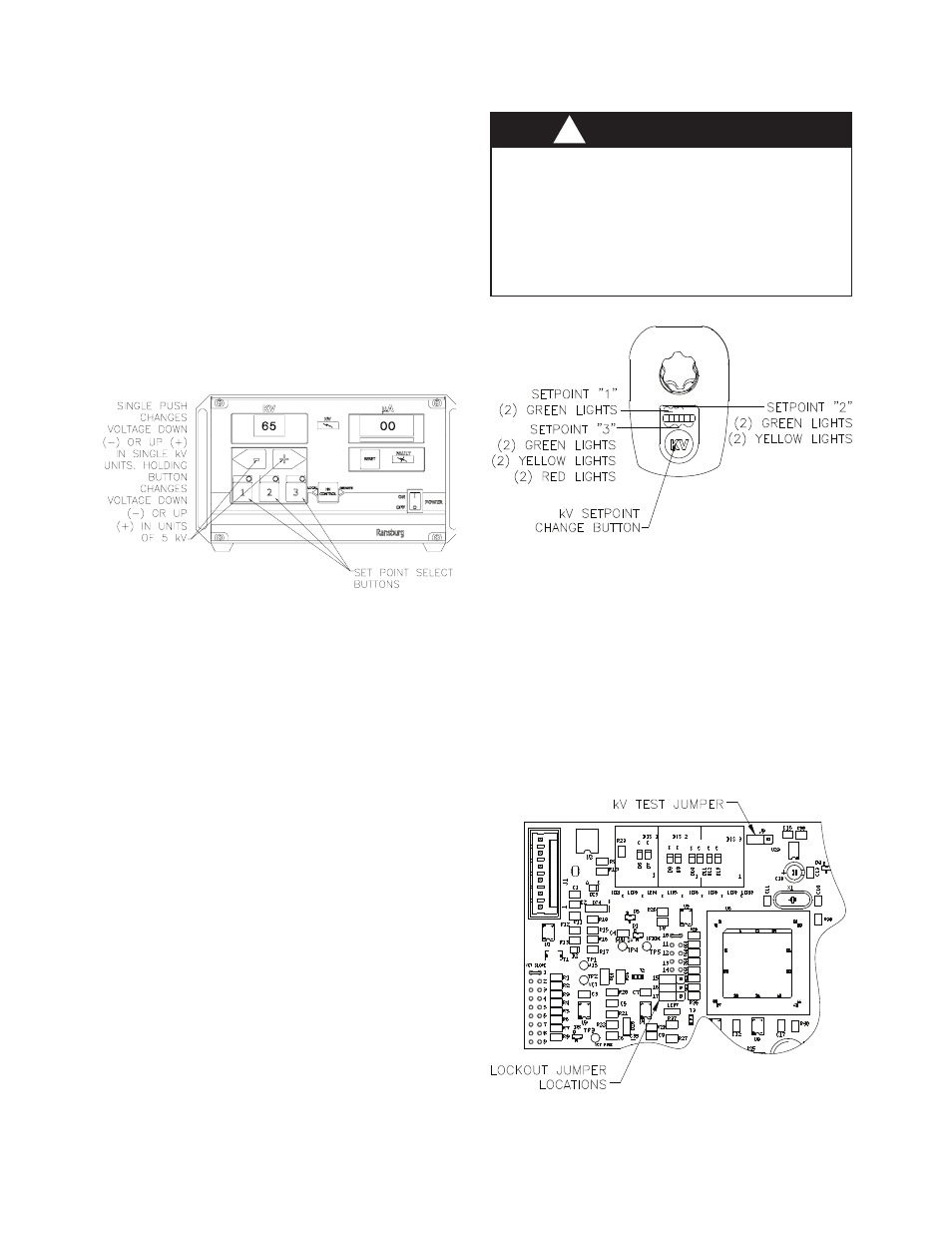
When a kV setpoint button is pressed, the light
above the button will light and the kV display will
show the present voltage for that setpoint. This
indicates the unit is set to spray at that setpoint.
To adjust the kV for the present setpoint, press
the + or - setpoint adjust buttons.
When the + or - setpoint adjust buttons are held
in longer than 1 second, the kV display will be-
gin incrementing or decrementing in units of 5
instead of 1.
DO NOT turn the applicator off using the
applicator button in place of interlocking with
a solvent supply for flushing. The applicator
must be interlocked with solvent supply such
that when the solvent is on to flush the appli-
cator, there is no kV at the applicator.
W A R N I N G
!
Figure 6: Changing Setpoint
Changing the Setpoint at the
Applicator
To change the setpoint at the applicator, the ap-
plicator must NOT be triggered. By pushing the
kV button on the rear cover of the applicator, the
setpoint will change. If there are 2 green lights lit,
setpoint 1 is active. If 2 green lights and 2 yellow
lights are lit, setpoint 2 is active. If all lights are lit
(2 green lights, 2 yellow lights, and 2 red lights)
setpoint 3 is active.
kV to the applicator can be turned off by pressing
the applicator kV button in for 2-3 seconds. This
can be done whether the applicator is triggered
or not and is useful if the kV needs to be turned
off for spraying into recessed areas. When the
kV is disabled in this manner, the kV meter will
read zero, OFF will be displayed in the microamp
meter and all kV setpoint indicator lights will be
disabled. Pressing the kV button in for another
2-3 seconds turns the kV to the applicator back on.
Figure 7: View of Rear Cover
LOCKOUTS
There are lockouts that may be done at the PC
board (see Figure 8). These lockouts may be used
individually or in combination as required. If the
jumpers are disconnected, the original functions
are re-enabled. After changing any jumpers, the
AC power must be cycled for the new setting to
take affect.
Figure 8: Lockout Jumper Location
AH-06-01.13