Fig. 1-16 using an optical fiber adaptor – Gentec-EO UP and XLP12 User Manual
Page 40
Version 5.0
Ultra Series UP Instruction Manual
Gentec Electro-Optics Inc. All rights reserved
36
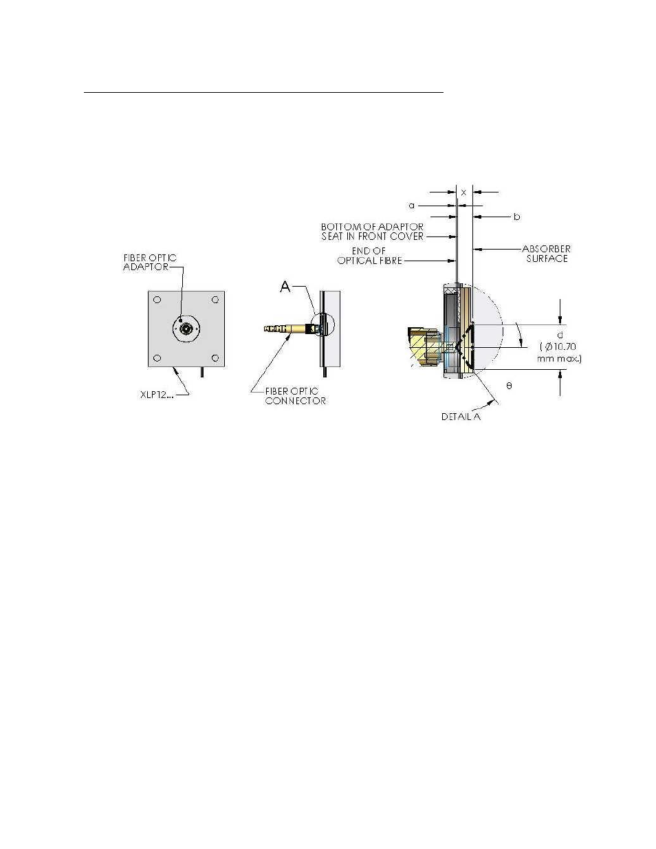
Appendix C: Using the XLP12 with an optical fiber adaptor:
When fitted with an appropriate adaptor, such as Gentec-
EO’s FC Optical Fiber Connector, the
XLP12 can be used to measure the output of an optical fiber. When using an optical fiber
adaptor, it is the user's responsibility to ensure that the entire output of the fiber is incident upon
the detector's absorbing surface. Figure 1-10 and the following inequation are provided as a
guide to verify this.
FIG. 1-16 USING AN OPTICAL FIBER ADAPTOR
For the XLP12, the distance in mm between the absorbing surface and the adaptor seat is b =
3.75 ± 0.5. The diameter in mm corresponding to 80% of the absorbing surface (80% is a
common value for allowing sufficient margin to avoid edge effects) is d = 10.7. The acceptance
angle
of the fiber is specific to the user’s fiber, as is the value of a, the distance in mm between
the end of the fiber and the interface between the adaptor and its seat on the detector. This
value can be measured once the user’s fiber is connected to the fiber adaptor (a typical value
may be
a
= 0.2 mm). Once known, the values
and a can be entered in the following
inequation:
4 tan
5.35
a
,
Where, 5.35 is d/2. If the inequation is verified, then it is safe to consider that the light cone,
having a height x = a + b and a maximum diameter d, exiting the fiber is entirely incident on 80%
of the measuring surface of the detector.