Up19k- …-w5 – Gentec-EO UP and XLP12 User Manual
Page 19
Version 5.0
Ultra Series UP Instruction Manual
Gentec Electro-Optics Inc. All rights reserved
15
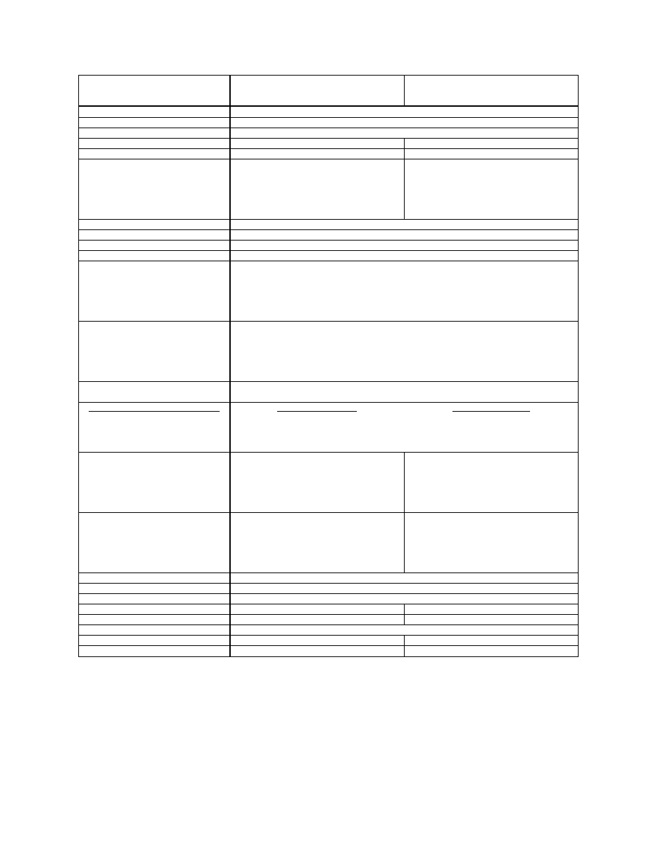
UP19K-
…-W5-…
UP19K-15S / 30H / 50L /
50F / 50W / 50DI -W5
Without PCB
UP19K-15S / 30H / 50L /
50F / 50W / 50DI -W5
With PCB
Effective Aperture Diameter
17 mm
Spectral Range
190 nm
– 10 µm
Calibrated spectral range
a
0.248
– 2.5 µm
Power Noise Level
1 mW
0.2 mW
Typical Rise time (0-95%)
5 s (1.4 s with anticipation)
1.4 s (with anticipation)
Typical sensitivity
0.65 mV/W
15S: 400 mV/W
30H: 200 mV/W
50L: 120 mV/W
50F: 120 mV/W
50W: 120 mV/W
50DI: 120 mV/W
Calibration Uncertainty
± 2.5 %
Linearity with Power
± 2 %
Repeatability (Precision)
± 0.5 %
Power Resolution
± 0.5 %
Max. Average Power
15S: 15 W
30H: 30 W
50L: 50 W
50F: 50 W
50W: 50 W
50DI (stainless steel): 50 W
Max. Average Power (1 min)
(cooling: minimum 3 min)
15S: 30 W
30H: 60 W
50L: 85 W
50F: 85 W
50W: 85 W
50DI (stainless steel): 85 W
Max. Average Power Density
1.064 µm, 10 W CW
100 kW/cm
2
Pulsed Laser Damage Thresholds
1.064 µm, 150 µs, 10 Hz
1.064 µm, 7 ns, 10 Hz
532 nm, 7 ns, 10 Hz
248 nm, 26 ns, 10 Hz
Max. Energy Density
100 J/cm
2
1.1 J/cm
2
1.1 J /cm
2
0.7J /cm
2
Peak Power Density
667 kW/cm
2
157 MW/cm
2
157 MW/cm
2
27 MW/cm
2
Dimension (mm)
15S: 50(H) x 50(W) x 20.6(D)
30H: 50(H) x 50(W) x 56.3(D)
50L: 76.2(H) x 76.2(W) x 74.7(D)
50F: 54.2(H) x 54.2(W) x 55.6(D)
50W: 50(H) x 50(W) x 33(D)
50DI: 50(H) x 50(W) x 33(D)
15S: 50(H) x 50(W) x 25.6(D)
30H: 50(H) x 50(W) x 61.3(D)
50L: 76.2(H) x 76.2(W) x 79.7(D)
50F: 54.2(H) x 54.2(W) x 60.6(D)
50W: 50(H) x 50(W) x 38(D)
50DI: 50(H) x 50(W) x 38(D)
Weight (head only)
15S: 0.16 kg
30H: 0.21 kg
50L: 0.48 kg
50F: 0.25 kg
50W: 0.24 kg
50DI: 0.42 kg
15S: 0.20 kg
30H: 0.25 kg
50L: 0.52 kg
50F: 0.29 kg
50W: 0.28 kg
50DI: 0.46 kg
Minimum Cooling Flow
b
0.5 liter/min
Recommended Cooling Flow
b
1.0 liter/min
Cooling
Heat sink / fan / water
Recommended load Impedance
100 kΩ
10 MΩ
Output Impedance
N. A.
≤ 50 Ω
Linearity vs beam dimension
± 0.5 %
PCB electrical supply
N. A.
+12 to +16 V regulated
Max outpul signal
N. A.
80 % of PCB electrical supply
a
The calibrations at 2.1 to 2.5 µm are on special request only.
b
Water temperature ≤ 22°C, 1/8 NPT compression fittings for ¼ inch semi-rigid tube.
Specifications subject to change without notice.