Hml 110 – Liquid Controls HML110 IOM User Manual
Page 26
HML 110
26
110_EN_LC_5_3_6X.doc
(POS. 6.3) Duty cycle value for pulses/frequency output [Duty cycle=% XX]
The duty cycle function defines the time ratio between ON and OFF state when frequency output is
used: 50% means that the ON phase will equal that of the OFF phase, 60% means that the ON phase
will be 60 % and the OFF phase will be 40% of the total cycle time. When the pulse outputs are used,
the duty cycle defines the OFF phase, this is because the ON phase is already set with the "PULSE
DURATION" function ( see Main menu “2 - SCALE” ). In this case, for example, the duty cycle is set at
50% and the pulse duration at 50ms, the OFF phase will be the same of the ON phase. The formula
to calculate the minimum time of the OFF phase and the time of total cycle is the following:
T. total cycle= 100 x (pulse duration in ms)/ (duty cycle)
T. OFF phase = T. total cycle - pulse duration
N.B.: When using the function in frequency mode, DO NOT set the duty cycle to 0. If the value of the
function is set to 0 the emission of the pulses occurs in synchronous mode with the flow rate. The
function is active only if one of the outputs is set on pulse and/or frequency function.
(POS. 6.4) Current output option and range
[Out mA=X_XX±XXX]
This function sets the current output N.1. This function is optional and will not appear unless the
option has been requested.
There are three fields to modify for this function:
• Scale
zero:
4 or 0 mA
• Full
scale:
20 or 22 mA
• Field:
+ = positive, - = negative,
± = both, -0+ = central zero scale
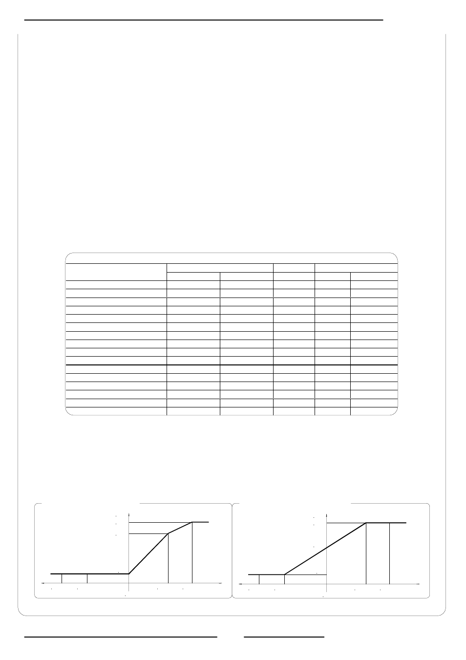
The values corresponding to the scale points are shown in the following chart:
In hardware alarm conditions “HW ALARM” (interrupted coils, empty pipe, measure error) the current
value is programmed by the function “mA v.fault” (pos. 4.5) and it is expressed as percentage of a
fixed current range, where: 0% = 0 mA and 110% = 22 mA.
CURRENT VALUES IN mA ASSOCIATE TO THE % VALUE OF FULL SCALE
REVERSE FLOW VALUE
ZERO
DIRECT FLOW VALUE
POSSIBLE FIELD
≤ -110%
-100% 0%
+100%
≥+110%
OutmA = 0 - 20 +
0
0
0
20
20
OutmA = 0 - 22 +
0
0
0
20
22
OutmA = 4 - 20 +
4
4
4
20
20
* OutmA = 4 - 22 +
4
4
4
20
22
OutmA = 0 - 20 -
20
20
0
0
0
OutmA = 0 - 22 -
22
20
0
0
0
OutmA = 4 - 20 -
20
20
4
4
4
OutmA = 4 - 22 -
22
20
4
4
4
OutmA = 0 - 20 ±
20
20
0
20
20
OutmA = 0 - 22 ±
22
20
0
20
22
OutmA = 4 - 20 ±
20
20
4
20
20
OutmA = 4 - 22 ±
22
20
4
20
22
OutmA = 0 - 20 –0+
0
0
10
20
20
OutmA = 0 - 22 –0+
0
1
11
21
22
** OutmA = 4 - 20 –0+
4
4
12
20
20
OutmA = 4 - 22 –0+
4
4.8
12.8
20.8
22
* Example 1: out 4-22 +
** Example 2: out 4-20 –0+
22 mA
20 mA
-110% F.S.
-100% F.S.
+100% F.S. +110% F.S.
zero
4 mA
I (mA)
I (mA)
20 mA
-110% F.S. -100% F.S.
+100% F.S. +110% F.S.
zero
12 mA
4 mA