Output 0/4-20ma outputs wiring – Liquid Controls HML110 IOM User Manual
Page 11
HML 110
11
110_EN_LC_5_3_6X.doc
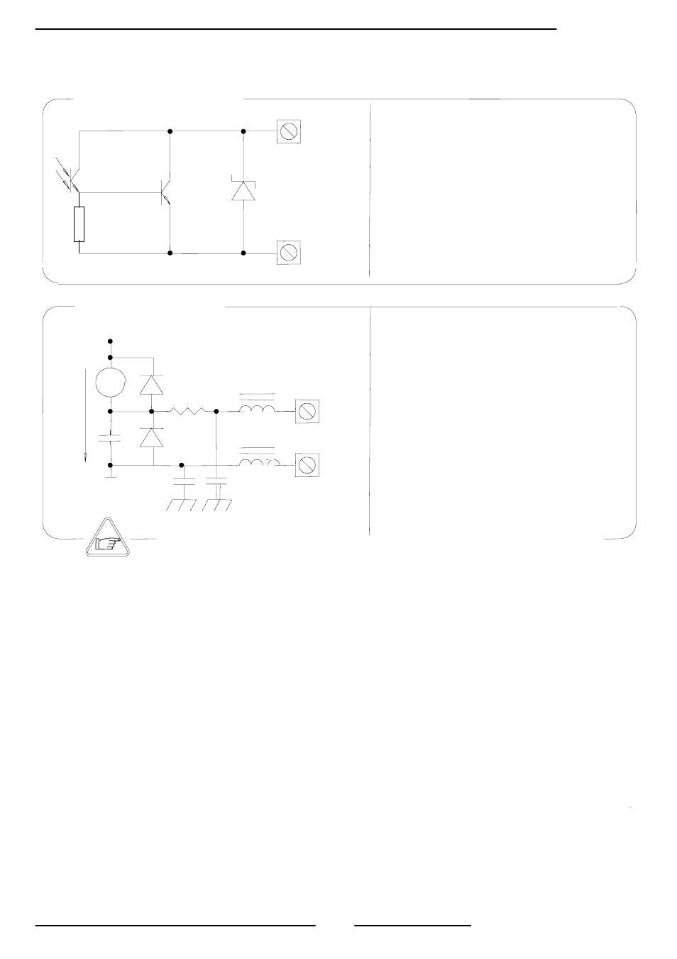
24V COMMON
+24V INTERNAL
0/4..20mA OUT
mA
9 (+)
10 (-)
I
Opto-insulated output
Maximum load: 1000 ohm
Maximum voltage without load: 27 Vdc
Refresh frequency is the same of the sample
frequency of the connected sensor
Protected against persistent over voltages to
maximum 30 Vdc
There is a Converter load CHECK on the 4 - 20mA output; to disable this
function set the value "mA Val. Fault" to 0 (Pos. 4.5, see page 15)
Before starting up the equipment please verify the following:
Power supply voltage must correspond to that specified on the data plate
Electric connections must be completed as described at page 7-8
Ground (earthed) connections must be completed as specified on page 7
Verify periodically:
The integrity of the power supply cables, wiring and other connected electrical
parts
The integrity of the converter’s housing (this must not have dents or other
damage that may compromises it’s hermetical sealing)
The tightening of the sealing elements (cable glands, covers, etc.)
The integrity of the front panel (display and keyboard), any damage may
compromise the equipment sealing
The mechanical fixing of the converter to the pipe or wall stand
Output 0/4-20mA
OUTPUTS WIRING
CONVERTER START UP AND MAINTENANCE INSTRUCTIONS
Output on/off 1250
Opto-insulated output with floating collector and
emitter terminals freely connectable
Maximum switching voltage: 40 Vdc
Maximum switching current: 100mA
Maximum saturation voltage between collector and
emitter @100mA: 1,2V
Maximum switching frequency (load on the
collector or emitter, RL=470
Ω, VOUT=24Vdc):
1250Hz
Maximum reverse current bearable on the input
during and accidental polarity reversion (VEC):
100mA
Insulation from other secondary circuits: 500 Vdc
16 (out1)
18 (out2)
17 (out1)
19 (out2)
43V