Display flags and led warning interpretation – Liquid Controls HML110 IOM User Manual
Page 12
HML 110
12
110_EN_LC_5_3_6X.doc
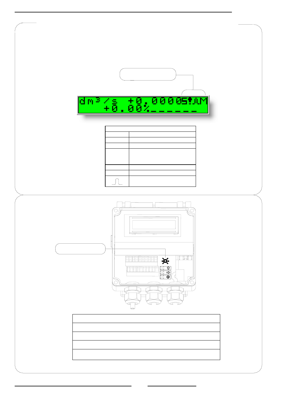
DISPLAY FLAGS AND LED WARNING INTERPRETATION
FLAG INTERPRETATION
FLAG
DESCRIPTION
M
Alarm max activated
m
Alarm min activated
!
- Interruption coils circuit
- Segnal error
- Empty pipe
C
Calibration running
S
Simulation
Pulse output saturation (reduce
TIME PULSE )
FLAGS
LED
LED INTERPRETATION
PERMANENT LIGHT: initialisation
FLASHING LIGHT ( 1 sec.): normal function
FLASHING LIGHT (<1 SEC.): alarm on
The LED signals the alarm status only if the display shows one of the
suitable visualisation screens as shown on page 14
At ‘Power on’ of the converter, the user will see the following display screen. In the top right
hand corner there may be a range of symbols. The symbols can be interpreted from the table
below. Interpretation of the flashing LED can be made from the LED Interpretation table at the
bottom of this page
- Gear Plate Selection Guide (24 pages)
- MS Meters (40 pages)
- MA4 Meter (32 pages)
- M-MA Meters (28 pages)
- HMS3700 & HMS3770 Insertion Sensors LC Mag Insertion (8 pages)
- HMS501, HMS600, HMS1000, HMS2400, HMS2500, and HMS5000 LC Mag IOM (8 pages)
- CIM100 (16 pages)
- Rate of Flow (4 pages)
- HML4-F1 - LCMag (40 pages)
- LCRII Install E3650-E3651 Series (40 pages)
- LCR-II Setup & Operation (60 pages)
- LCRII Menu Map (2 pages)
- LCR-II - Quick Reference (2 pages)
- LCR Install (24 pages)
- LCR Setup & Operation (60 pages)
- LCR 600 Install (36 pages)
- LCR600 Wiring Schematic (1 page)
- LCR 600 Setup & Op (68 pages)
- LCR 600 - Quick Reference (2 pages)
- FlightConnect 600 (52 pages)
- FlightConnect 600 QR (2 pages)
- LCR-II Installation E3655-E3656 (36 pages)
- LCRII E3651-E3656 Wiring Schematic (1 page)
- DMS Installation (20 pages)
- DMS Setup (84 pages)
- DMS Delivery (52 pages)
- DMS i1000 Quick Reference - DMS Delivery (2 pages)
- DMS Office (52 pages)
- DMS i1000 EZConnect Operators (36 pages)
- DMS i1000 Quick Reference - EZConnect (2 pages)
- EZConnect Office (44 pages)
- FlightConnect Office (36 pages)
- FlightConnect Setup Guide (8 pages)
- DB Manager (20 pages)
- POD (16 pages)
- Dual Meter Multiplexer (8 pages)
- Differential Pressure Transducer (12 pages)
- XL LED Display E1615_E1616_E1617_E1618 (20 pages)
- SCAMP (20 pages)
- WinHost Operation (44 pages)
- SP714-S2i (12 pages)
- HML210 IOM - LCMag (44 pages)
- Sponsler T675 - Cryogenic System Register (54 pages)
- Sponsler IT400 Electronic Register (40 pages)