Wiring - reset switch kit, Reset switch 30' shielded cable, Remote display pcb board – Liquid Controls XL LED Display E1615_E1616_E1617_E1618 User Manual
Page 16
wiring the Reset Switch kit (Pn 82592) -
moDELS E1617 & E1618
The Reset Switch Kit (P. N. 82592) is required for the installation of XL LED Remote Display models E1617 and
E1618. The reset switch resets the XL LED Remote Display to zero between deliveries.
The reset switch can not zero out the totalizer while a delivery is active. To zero the display totalizer, the reset switch
must be pushed when the display is not receiving a pulse output. The switch must be pushed and held for two
seconds before the display will reset to zero.
Reset Switch kit includes:
• ½", 4-port conduit box (2)
• Port plugs (2)
• Cord grips (3)
• Reset switch
• Nipple
• 30' shielded cable
to install the Reset Switch kit:
1. Remove the rear panel from the LectroCount XL LED Remote Display.
2. Remove the cord grip and shielded cable (supplied with the XL LED Remote
Display) from the port at the bottom of the housing.
3. Attach a 4-port conduit box to the empty port on the bottom of the unit.
4a. If mounting the reset switch directly to the XL LED Display, screw the reset
switch into a port on the 4-port conduit box.
4b. If mounting the reset switch remotely, mount the second 4-port conduit box
and screw the reset switch into a port on the second 4-port conduit box.
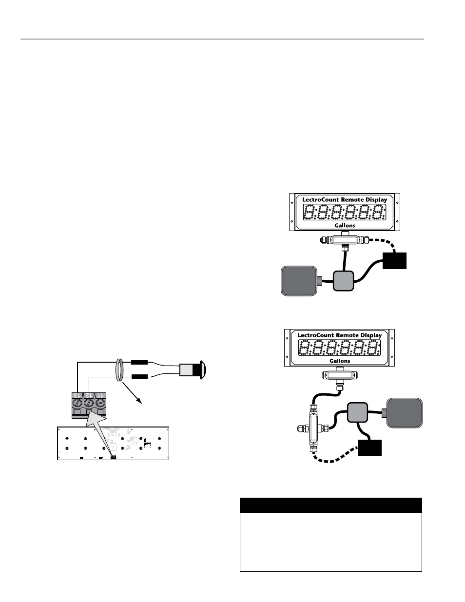
5. Screw the cord grips into the conduit box(es). Use diagrams on the right to
determine the best ports for cord grips.
6. Route the 30’ shielded cable (supplied with the reset switch kit) from the
reset switch through the conduit box(es) into the XL LED Remote Display
housing.
7. Connect the shielded cable wires to the reset switch inside its conduit
box and to terminals 12 and 13 on the J2 terminal block on the XL LED
Remote Display PCB.
8. Route the shielded cable (supplied with the XL LED Remote Display) out
of the display housing and through the conduit box(es).
9. Replace the rear panel of the display. page 18 Torque Specifications
10. Install and wire the calibrated pulse output device. page 10, 11,
or 12
WIrInG - reset sWItch kIt
Optional Power
Connection
CALIBRATED
PULSE
OUTPUT
DEVICE
EXTERNAL
POWER
SOURCE
Junction
Box
Reset
Switch
Optional Power
Connection
Reset
Switch
CALIBRATED
PULSE
OUTPUT
DEVICE
Junction
Box
EXTERNAL
POWER
SOURCE
Reset Switch
30' Shielded
Cable
RES
COM
Remote Display PCB Board
11
12
13
J2
LectroCount XL LED Remote Displays are assembled
and shipped ready for final cable termination. If the
display’s pre-installed shielded cable is removed
during installation, be sure to secure the cable and
tighten the cover so the vapor seal is maintained. See
page 18 for proper torque specifications.
Secure Cable and Tighten Cover
16