Model e1618 - wiring, Wiring model e1618 (lcmag™) – Liquid Controls XL LED Display E1615_E1616_E1617_E1618 User Manual
Page 11
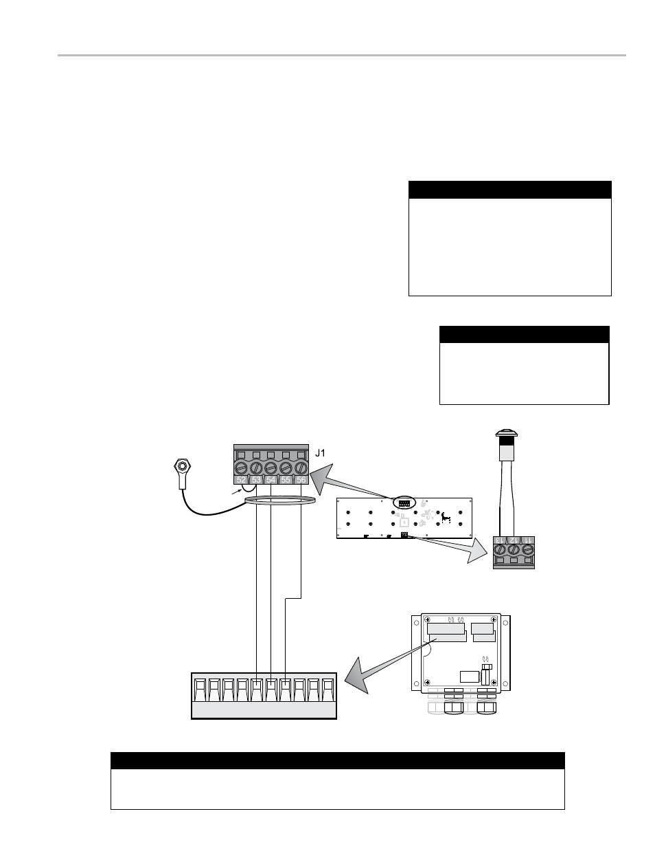
wiring model E1618 (LCmag™)
Model E1618 of the LectroCount XL LED Remote Display will accept the calibrated pulse output of the LCMag
HML210 converter.
Since the HML210 does not have an output signal to reset the LED Remote Display, a Reset Switch Kit (PN 82592) is
required for this application. The Reset Switch Kit resets the XL LED Remote Display to zero between deliveries.
to wire the LectroCount XL LED Remote Display model E1618 to the hmL210 Converter:
1. Install Reset Switch Kit. page 16
2. Open the LCMag HML210 converter. Refer to manual IEM200-10 for specific
instructions regarding opening, closing, and sealing the converter.
3. Route the shielded cable through a cable gland and into the HML210
housing.
4. Connect the display’s shielded cable wire to the designated terminals on
the HML210 CPU board
• XL LED terminal 53 (red wire) to HML210 terminal 15
• XL LED terminal 54 (white wire) to
HML210 terminal 16
• XL LED terminal 56 (black wire) to
HML210 terminal 17
5. Tighten the cable gland and close the HML210 converter.
moDEL E1618 - wIRInG
A jumper is required between terminal 52 and terminal 53 on the display’s J1 terminal block. Display
units from the factory will include the jumper. When rewiring, ensure that this jumper is in place.
J1 Jumper - LectroCount XL LED Remote Display
LCMag™ PCB
11 12 13 14 15 16 17 18 19 20
Remote Display
PCB Board
GND
/Blac
k (56)
GND
/Blac
k (17)
B/White
(54)
PWR
/R
ed
(53)
B/White
(16)
PWR
/R
ed
(15)
Jumper
Reset Switch
RES
COM
11
12
13
J2
Shieled cable
ground wire
grounded to
remote display
PCB board
The LectroCount XL LED Remote Display
is supplied with a 30 foot 4-wire shielded
cable with 22 gauge wire. If alternate
cabling is required, Liquid Controls
recommends a similar 4-wire shielded
cable with 22 gauge wire or larger and a
maximum cable length of 30 feet.
Shielded Cable
If the power to the HML210
exceeds 24 VDC, then the remote
display should be powered from
Pin 32 on J8, 5 VDC.
24 VDC Power
11